


21
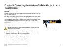
Chapter 5: Connecting the Wireless-B Media Adapter to Your TV and Stereo
Placement Options
Wireless-B Media Adapter
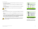
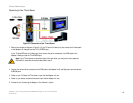
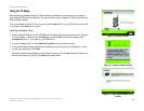
2. Connect the power adapter to the Adapter’s Power port and an electrical outlet.
3. Press the Power button on the Adapter’s front panel.
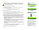
If the Adapter connects to your wireless network, the Wireless LED will light up. Go to step 4.
If the Adapter connects to your wired network, the Ethernet LED will light up. If it does not, then push the
Uplink button on the Adapter’s back panel. Power the Adapter off and back on again. Make sure the cable
connections are secure.
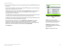
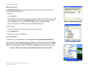
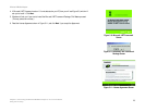
4. If you used the Setup Wizard to set up the Adapter, then the Adapter Utility on your PC will automatically find
the Adapter on your wireless or wired network. The main menu of the Media Navigator will appear on your TV.
(This may take a few seconds).
If you want to set up the Adapter using your TV, proceed to the “Using the TV Setup” section.
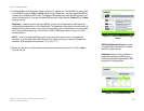
5. Insert the batteries into the remote control, and use the arrow and Select buttons to select songs and
pictures.
Proceed to the “Placement Options” section.
Placement Options
To protect the cables attached to the Adapter’s back panel, snap the included cable hood into place. The dark
gray section of the cable hood faces away from the antenna.
There are two ways to place the Adapter. The first way is to place the Adapter horizontally on a surface, so it sits
on four small rubber feet.
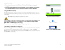
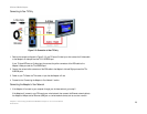
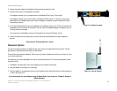
The second way is to stand the Adapter vertically on a surface (see Figure 5-5). To use the stand option, follow
these instructions:
1. The Adapter includes a base. Insert the end opposite to the antenna into the base.
2. Snap the Adapter into the base, so it fits snugly.
3. Place the Adapter in an appropriate location, and if necessary, adjust the antenna so that it points straight up
in the air (see Figure 5-5).
If you have already set up the Adapter using the Setup Wizard, then proceed to “Chapter 6: Using the
Media Navigator.”
Figure 5-5: Vertical Position
Figure 5-4: Connect the Power