


— 14 —
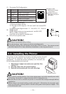
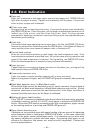
(1) Connector Pin Configuration
No. Signal Function
1FG Frame Ground
2 DRAWER 1 Drawer 1 drive signal
3 DRSW Drawer switch input
4 VDR Drawer drive power supply
5 DRAWER 2 Drawer 2 drive signal
6 GND Common ground on circuits
61
Connector used:
TM5RJ3-66 (Hirose)
or equivalent
Applicable connector:
TM3P-66P (Hirose) or
equivalent
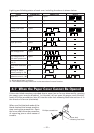
VDR
1
2
3
4
5
6
VDR
5V
CAUTION!
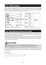
■ No output is produced while printing.
■ The cash drawers 1 and 2 cannot be driven simultaneously.
■ A solenoid used for the cash drawer should be of 24 Ω or more. The output current
should be kept at 1A or less; otherwise, breakdown or burning could occur.
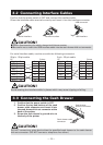
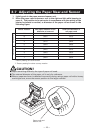
CAUTION!
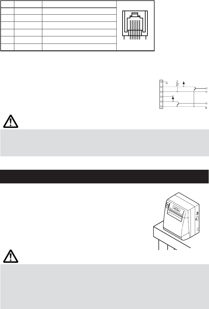
■ When used in vertical position, the printer ejects paper not to fall naturally even with
full cutting. Be careful in using the printer built in equipment, etc.
■ Ensure that the wall on which the printer is mounted has enough strength before
installation.
■ When using in horizontal setting, avoid cutting full. Otherwise, the cut paper may
drop into the cutter and may result in double cutting and narrow pieces of paper. This
may cause paper jam.
(2) Electrical characteristics
1) Driving voltage: 24 VDC
2) Driving current: Approx. 1A max. (shall not exceed 510
ms.)
3) DRSW signal: Signal levels: “L” = 0 to 0.5 V, “H” = 3 to 5 V
(3) DRSW signal
DRSW signal status can be tested with the DLE+EOT,
GS+a, or GS+r command or
at pin 34 on the parallel interface port.
(4) Drive Circuit (printer side)
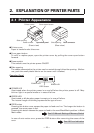
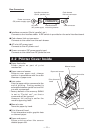
3.4 Installing the Printer
The printer can be installed horizontally, vertically, and on the wall.
At the time of shipment, the printer is set for horizontal
installation. To install the printer vertically or on the wall, the
following adjustments are required.
1. Adjustment of paper near-end sensor position (See
section 3.7)
2. Anti-slip rubber feet (for vertical setting)
3. Optional wall-mounting kit (for wall-mounting)
Vertical position