iDP-3210 User’s Manual
CITIZEN
49
(8) Specifying the Bit Image Mode (ESC * m n1 n2 D1 - Dn)
Code : [1B]h + [2A]h + m + n1 + n2 + Dn
* {m= bit image mode (See the table below.)}
{0 ≤ n1 ≤ FF}
{0 ≤ n2 ≤ 02} Data is described in Hex code.
According to the bit image mode assigned in m, prints data in the bit image.
l The no. of dots printed is divided by 256, whose quotient is taken as n2 and residualas n1.
l The total no. of dots printed in the bit image is equal to n1 + (256 x n2).
l When bit image data have been input in excess of 1 dot/line (448 dots) position, the excess
data are discarded.
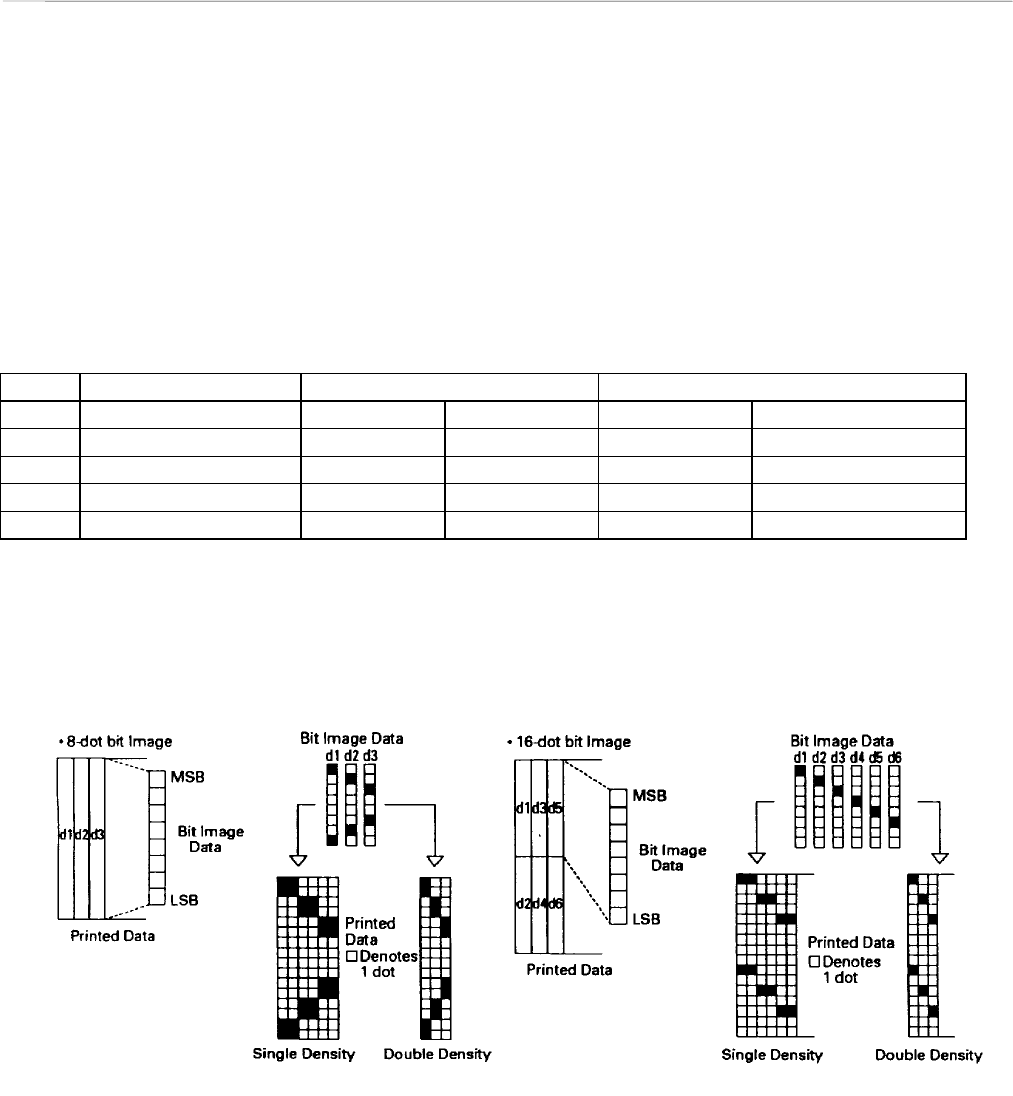
l In the bit image data (Dn), the bits subject to printing are taken as "1" and those not as "0".
l The bit image modes are shown as follows:
VERTICAL DIRECTION HORIZONTAL DIRECTION
m(Hex) MODE NO. OF DOTS DOT DENSITY DOT DENSITY MAX. NO OF DOTS
0 8-dot single density 8 78 DPI 77 DPI 224
1 8-dot double density 8 78 DPI 154 DPI 448
32 16-dot single density 16 156 DPI 77 DPI 224
33 16-dot double density 16 156 DPI 154 DPI 448
l When the value set in m (bit image mode) are out of conditions, the data following after n1 is
processed as printing data.
The relation between bit image data and printing dots are shown below.


