


4-6
Installing Hardware Options
Writer: Tom Erber Project: ProLiant 3000 Setup and Installation Guide Comments: 296908-002
File Name: E-CH04.DOC Last Saved On: 1/27/98 4:20 PM
COMPAQ CONFIDENTIAL - NEED TO KNOW REQUIRED
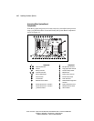
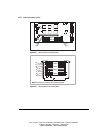
Accessing Other System Board
Components
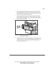
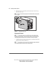
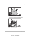
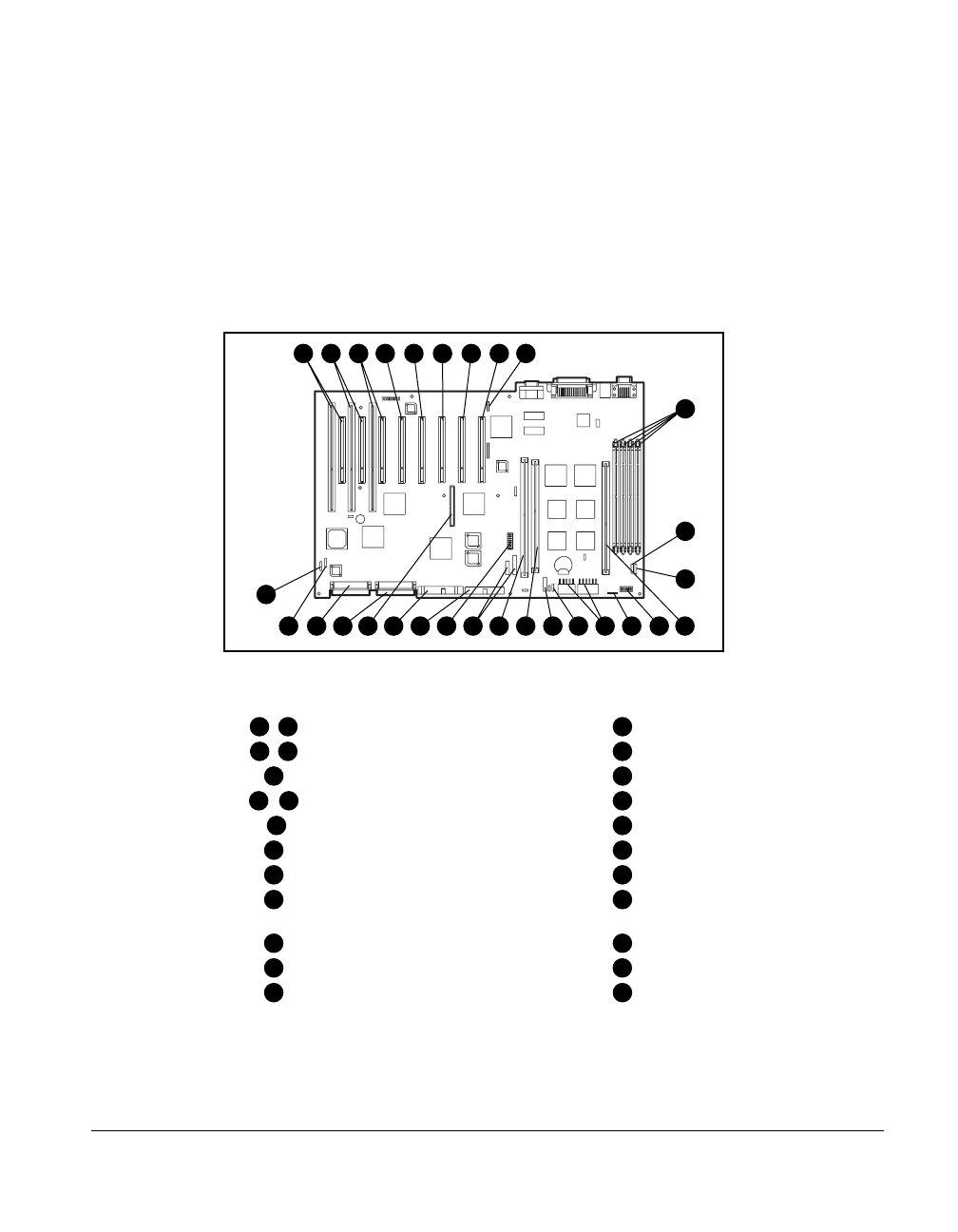
With the top panel and processor boards removed, as described in the previous
steps, you should be able to locate and identify the System Board components
shown in Figure 4-4.
18
14
15 16 19 20 9 2423 262510 11
29
28
2721
12
2217
2 4
5 6 7 8
13
31
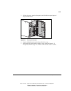
Figure 4-4.
System Board Features
# Component # Component
1
-
3
Shared PCI/EISA slots
19
IDE signal cable connector
4
-
8
PCI slots
20
Floppy signal cable connector
9
Memory board slot
21
Processor settings switch
10
,
11
Processor board slots
22
IMDconnectors
-
12
Memory DIMM sockets
23
Auxiliary power connector
13
CPU Fan header
24
External battery header
14
I/O Fan header
25
Power Connectors
15
Redundant I/O Fan header
26
Switch/Interlock Floppy Power
Connector
16
Internal SCSI connector - Channel A
27
System configuration switch
17
Internal SCSI connector - Channel B
28
Redundant CPU Fan header
18
I
2
O feature connector
29
CPU Fan header