


Chapter 5 Input/Output Interfaces
Compaq Deskpro 4000N and 4000S Personal Computers
First Edition – September 1997
5-8
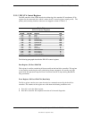
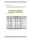
5.2.2 IDE CONNECTORS
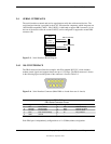
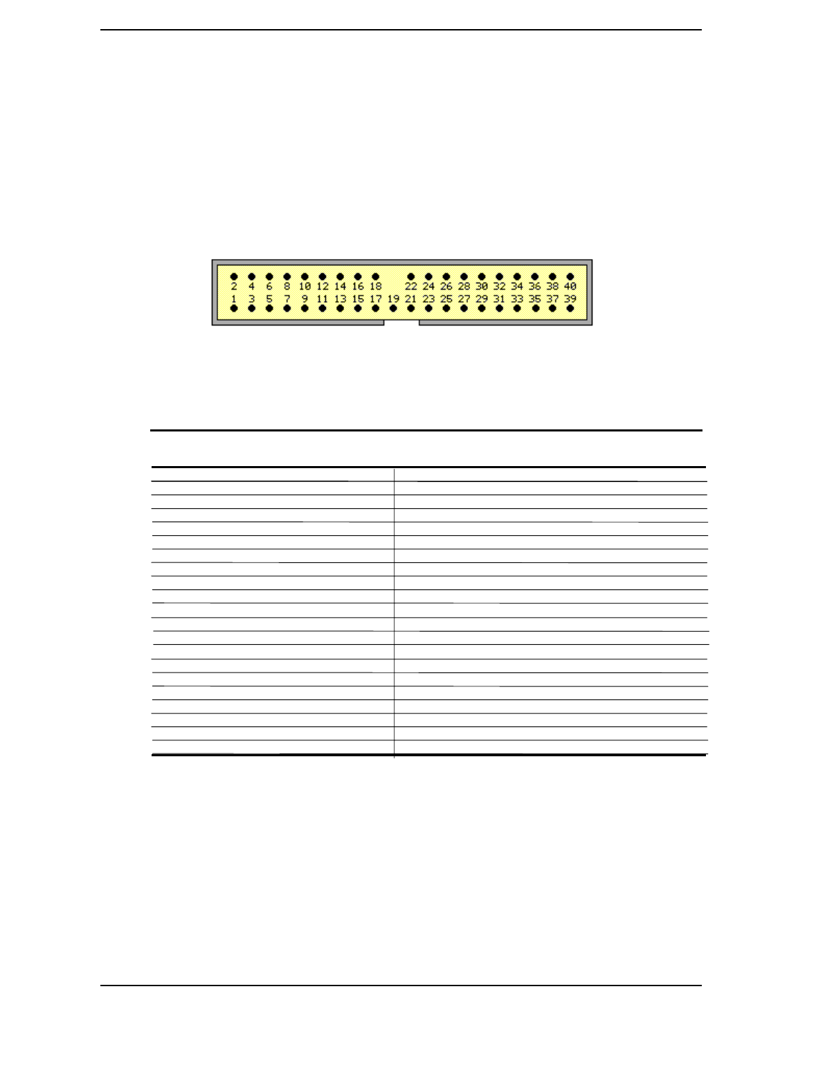
This system includes two standard 40-pin connectors and one 50-pin connector for IDE devices.
Devices attached to the 40-pin connectors obtain power through a separate connector. The 40-pin
connector is shown in the illustration below followed by the connector’s pinout.
Figure 5–1. 40-Pin IDE Connector.
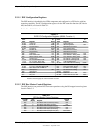
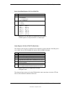
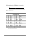
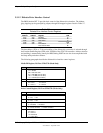
Table 5–5. 40-Pin IDE Connector Pinout
Table 5-5.
40-Pin IDE Connector Pinout
Pin Signal Description Pin Signal Description
1 RESET- Reset 21 DRQ DMA Request
2 GND Ground 22 GND Ground
3 DD7 Data Bit <7> 23 IOW- I/O Write
4 DD8 Data Bit <8> 24 GND Ground
5 DD6 Data Bit <6> 25 IOR- I/O Read
6 DD9 Data Bit <9> 26 GND Ground
7 DD5 Data Bit <5> 27 IORDY I/O Channel Ready
8 DD10 Data Bit <10> 28 CSEL Cable Select
9 DD4 Data Bit <4> 29 DAK- DMA Acknowledge
10 DD11 Data Bit <11> 30 GND Ground
11 DD3 Data Bit <3> 31 IRQn Interrupt Request [1]
12 DD12 Data Bit <12> 32 IO16- 16-bit I/O
13 DD2 Data Bit <2> 33 DA1 Address 1
14 DD13 Data Bit <13> 34 DSKPDIAG Pass Diagnostics
15 DD1 Data Bit <1> 35 DA0 Address 0
16 DD14 Data Bit <14> 36 DA2 Address 2
17 DD0 Data Bit <0> 37 CS0- Chip Select
18 DD15 Data Bit <15> 38 CS1- Chip Select
19 GND Ground 39 HDACTIVE- Drive Active (front panel LED) [2]
20 -- Key 40 GND Ground
NOTES:
[1] Primary connector wired to IRQ14, secondary connector wired to IRQ15.
[2] Pin 39 is used for spindle sync and drive activity (becomes SPSYNC/DACT-)
when synchronous drive are connected.