


4–40 Maintenance and Service Guide
Removal and replacement procedures
✎
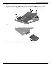
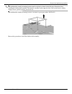
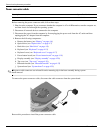
Due to the adhesive quality of the thermal material located between the fan/heat sink assembly and system board
components, you may need to move the fan/heat sink assembly from side to side to detach the assembly.
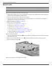
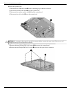
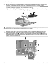
3. Turn the system board upside down with the fan assembly toward you.
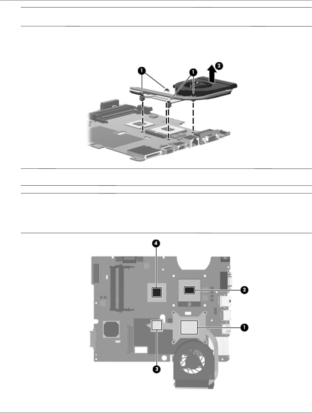
4. Loosen the four Phillips PM2.0x10.0 spring-loaded captive screws 1 that secure the fan/heatsink assembly.
Remove the fan/heat sink assembly 2 by lifting it straight up.
Å
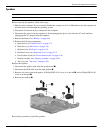
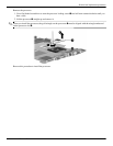
WARNING: To avoid damage to the processor, loosen the fan/heatsink screws in the 1-2-3-4 sequence indicated. Likewise,
tighten the screws in the same sequence when installing the fan/heatsink assembly.
✎
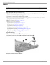
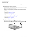
The thermal material must be thoroughly cleaned from the surfaces of the fan/heat sink and the system board
components each time the fan/heat sink is removed. Thermal grease is located on the section of the fan/heat
sink 1 that services the processor 2. Thermal pads are located on the section of the fan/heat sink 3 that services
the Northbridge chip 4. Replacement thermal grease and pads are included with all system board, fan/heat sink
assembly, and processor spare part kits.