


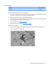
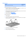
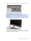

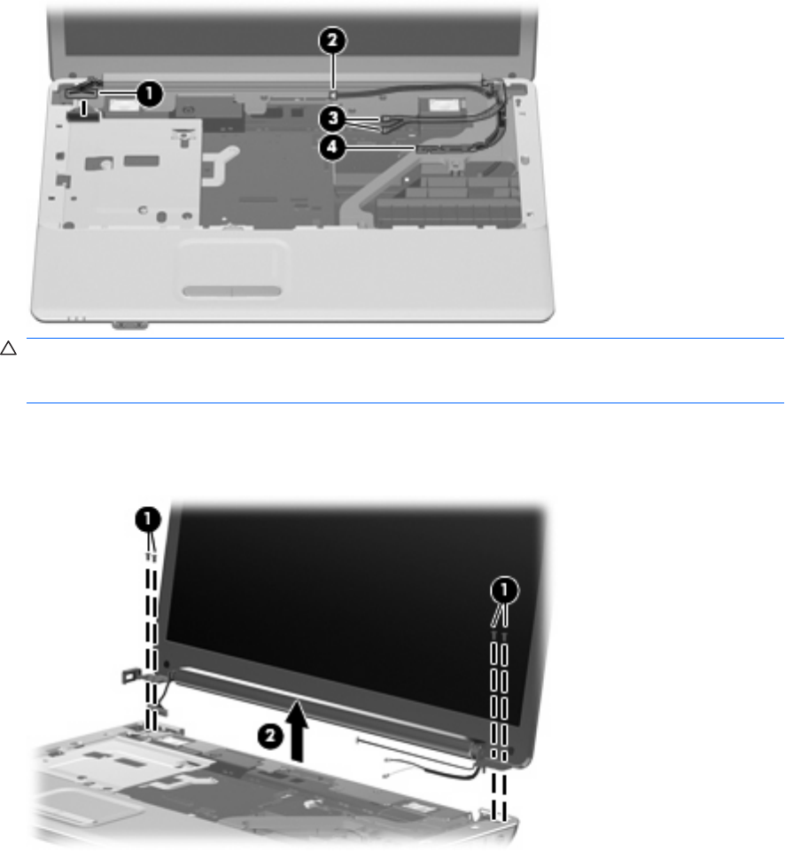
4. Remove the WLAN antenna cables (3) from the clips and routing channels (4) built into the top
cover.
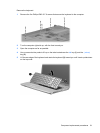
CAUTION: Support the display assembly when removing the following screws. Failure to support
the display assembly can result in damage to the display assembly and other computer
components.
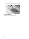
5. Remove the 4 Phillips PM2.5×7.0 screws (1) that secure the display assembly to the computer.
6. Lift the display assembly (2) straight up and remove it.
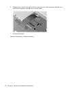
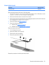
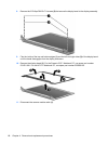
7. If it is necessary to replace any of the display assembly internal components, remove the 2 rubber
screw covers (1) on the display bezel bottom edge. The rubber screw covers are included in the
Display Rubber Kit, spare part number 531525-001.
Component replacement procedures 67