


iv
Figures
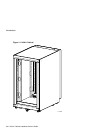
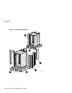
Figure 1-1 H9A11 Cabinet ...................................................................................................... 1–2
Figure 2-1 Unpacking the Cabinet ........................................................................................... 2–4
Figure 2-2 Installing the Ramps............................................................................................... 2–6
Figure 2-3 Deskidding the Cabinet .......................................................................................... 2–8
Figure 2-4 Removing and Replacing the Rear Lift-Off Door.................................................. 2–11
Figure 2-5 Removing and Replacing the Front Filler Panels................................................... 2–13
Figure 2-6 Pulling Out and Adjusting the Stabilizer Bar......................................................... 2–15
Figure 2-7 Removing and Replacing the Power Distribution Unit .......................................... 2–17
Tables
Table A-1 Field Replaceable Units (FRUs)..............................................................................A–1