


11
SECTION 2. INSTALLATION
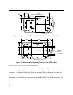
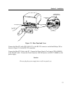
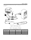
The installation of the IntelliStripe 380 Reader-Encoder consists of mounting the unit on a flat
surface, connecting the I/O RS-232 cable to the host serial port, the Auxiliary cable to a
peripheral device, and the Power Supply to the I/O cable and to a wall receptacle.
MOUNTING
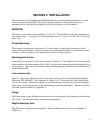
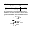
The bottom of the unit is shown in Figure 2-1 and 2-2. The IntelliStripe 380 may be mounted in
one of three ways: 1) foot pads, 2) set of mounting holes for 3 screws (4 x 40), and 3) 4 lock-in-
place slots.
Footpad Mounting
The footpads are mounted at the factory if it is the default. Simply place the unit on a level
surface with approximately 4 inches clearance from obstructions at the front of the unit for card
clearance. Leave enough room at the rear of the unit for cable clearance.
Mounting Hole Screws
Locate the 3 screw holes (4 x 40 screws) shown in Figure 2-1. The length of the screws depends
on the thickness of the mounting surface. Drill 3 holes in the mounting surface that match the set
of screw holes. The screws are mounted from under the mounting surface and into the bottom of
the IntelliStripe 380.
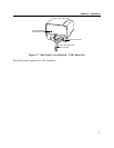
Lock-in-place-slots
Figure 2-2 shows the dimensions of the Lock-in-place slots, to be used with optional Baseplate
Mounting, P/N 16054403. (See Appendix A, Figure A-4.) The holes next to the lock-in-place-
slots are for inserts. The holes are placed over mounted inserts and the unit is pulled the length
of the slots forcing the thickness of the bottom plate to lock the unit in place. Dimensions of the
slots and inserts are shown in Appendix A.
Flange
The flange shown in the illustration may be used to screw the unit to the mounting surface using
a #4 screw. It can be used with any mounting configuration.
MagTek Mounting Plate
MagTek offers an optional mounting plate. The plate dimensions are shown in Appendix A,
Figure A-4.