


IntelliStripe 380
12
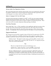
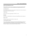
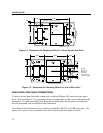
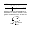
Foot Pads (4)
Mounting Screws #4-40 (3)
5.789
3.230
1.616
1.105
.546
Figure 2-1. Dimensions for Mounting Holes for 3-Screw Set and Foot Pads
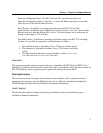
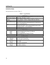
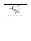
Lock-In-Place Slots (4)
Ø .125
Mounting
Flange (1)
(use with
Lock-In-Place
mounting holes)
4.330
.375 (4)
.959
.180 (4)
2.810
2.032
1.147
Figure 2-2. Dimensions for Mounting Holes for Lock-in-Place Slots
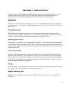
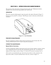
REAR PANEL AND CABLE CONNECTIONS
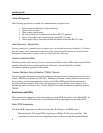
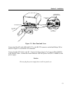
To access the rear panel and cable connections on the IntelliStripe 380, remove the rear panel
cover, shown in Figure 2-3, by squeezing the two mounting clips on the cover as indicated in the
illustration. To replace the back panel, insert the mounting clips into the guide slots and press
into the attachment slots as indicated in the illustration.
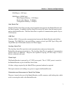
Also shown in the illustration are the Auxiliary and the Host RS-232 and USB connectors. The
ejector rod is used to remove jammed cards and is stored on the back panel as shown.