


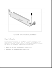
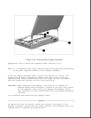
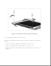
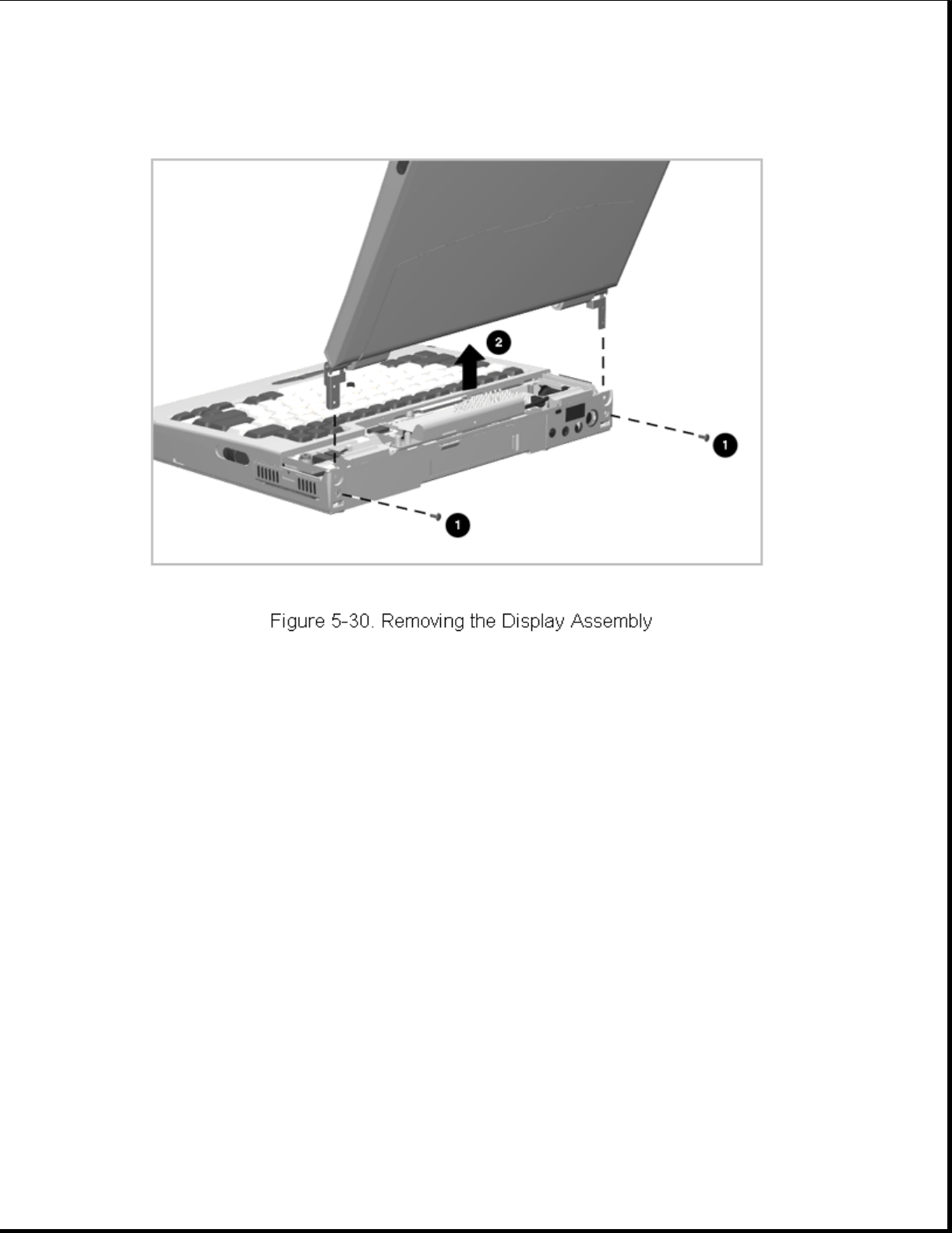
Reverse the above procedure to install the display assembly. Install the
appropriate logo to match the computer model (Section 5.4.1).
NOTE: It is important that these instructions be followed when replacement
of any part requires removal of the display assembly:
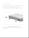
Slide the display assembly back in place and replace all screws. The
screws must be fully tightened to ensure that they do not touch the
expansion base sensor located near the left hinge. Failure to properly
seat the screws may prevent the unit from booting up.
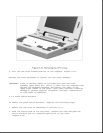
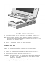
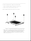
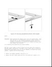
IMPORTANT: When installing the display, take care not to damage the
docking sensor switch actuator located in the left rear corner
of the computer. Also, route the display and speaker cables
very carefully to avoid interference with the display and power
switches.
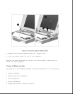
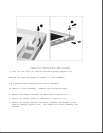
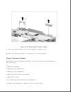
5.8.2 Removing and Installing the Display Bezel
>>>>>>>>>>>>>>>>>>>>>>>>>>>>>>>>> WARNING <<<<<<<<<<<<<<<<<<<<<<<<<<<<<<<<<
To reduce the risk of electric shock from contact with parts in the
display enclosure, ensure that all power sources to the display panel are
removed prior to opening the display bezel.