


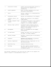
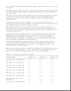

The following LCD panels are supported:
o 10.4-inch (26.4 cm) CSTN VGA Display (640 x 480)
o 11.3-inch (28.7 cm) CSTN SVGA Display (800 x 600)
o 10.4-inch (26.4 cm) CTFT VGA Display (640 x 480)
o 10.4-inch (26.4 cm) CTFT VGA Display (800 x 600)
o 11.3-inch (28.7 cm) CTFT SVGA Display (800 x 600)
o 12.1-inch (30.7 cm) CTFT SVGA (800 x 600)
o 12.1-inch (30.7 cm) CTFT 1024 x 768 Display
Both LCD panels have a controllable backlight intensity that can be
adjusted with a slide switch. The CSTN (dual scan) panels also have a
slide switch for contrast control.
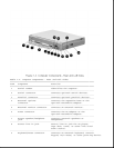
The LCD panel inverter cable plugs into an 8-pin connector on the
processor board. The LCD cable plugs into a connector on the system board.
The inverters and cables differ according to the display type and
manufacturer and cannot be interchanged. All of the display cables are
routed to the system unit in the vicinity of the clutches.
NOTE: It is important that these instructions be followed when replacement
of any part requires removal of the display assembly.
Slide the display assembly back in place and replace all screws. The
screws must be fully tightened to ensure that they do not touch the
expansion base sensor located near the left hinge. Failure to properly
seat the screws may prevent the unit from booting up.
NOTE: Use Fn+F4 hotkeys to switch between external, internal, and
simultaneous display. (The CSTN 800 x 600 does not support
simultaneous display.)
Display Bezel With Speakers
The display bezel attaches to the display unit with a snap action and is
secured with a screw at each corner. Screw covers are installed over the
screw heads. After removing these screws, use a Compaq bezel removal tool
to separate the bezel from the display assembly. The display bezel can be
removed without separating the display unit from the system unit.
The internal stereo speakers are 0.5-watt, 8-ohm, permanently installed in
the top corners of the display bezel and are installed as a unit with
cabling attached. The speaker cable is routed into the system unit and
connects to a 4-pin connector adjacent to the 30-pin LCD connector on the
system board. The CPU cover is easily removed from the system unit to
access this connector.
NOTE: Use Fn+F5 hotkeys to toggle speakers/headphones off and on.