


Removal and Replacement Procedures
Maintenance and Service Guide 5–29
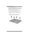
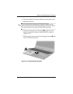
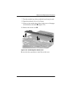
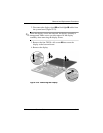
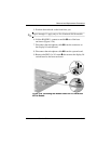
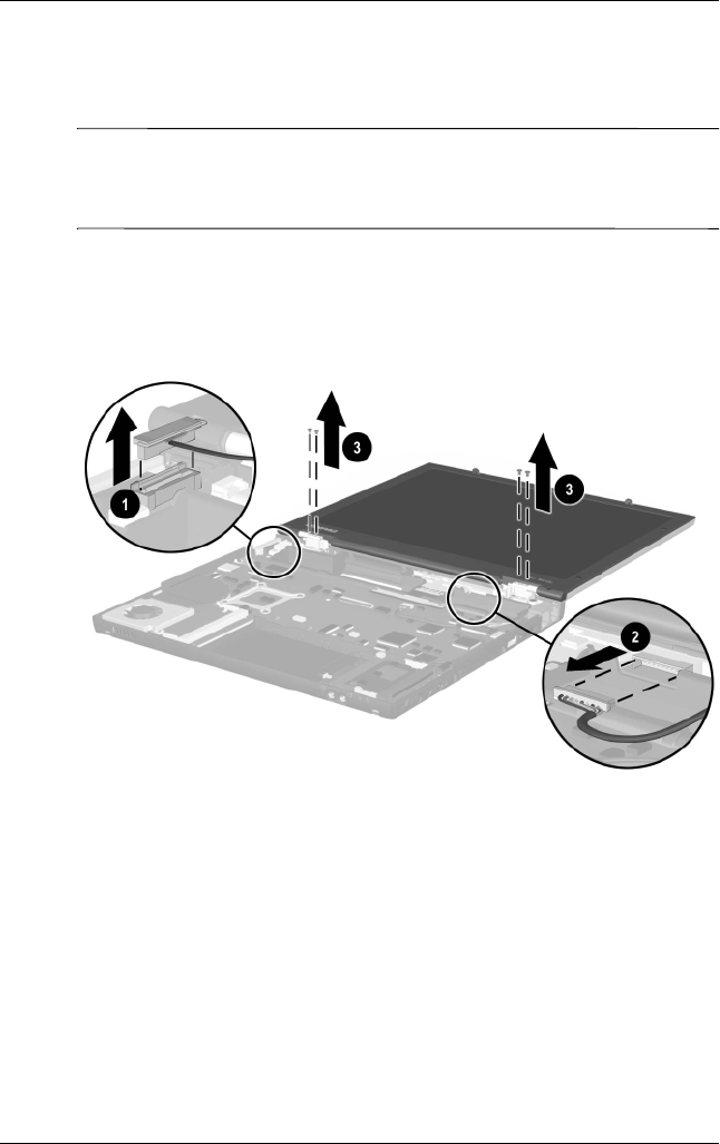
2. Disconnect the display signal 1 and backlight 2 cables from
the system board (Figure 5-23).
✎
When the display screws are removed, the display assembly is
unsupported. Make sure to provide support for the display
assembly when removing the display screws.
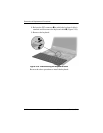
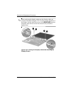
3. Remove the four TM2.0 × 6.0 screws 3 that secure the
display to the base enclosure.
4. Remove the display.
Figure 5-23. Removing the Display