


5–32 Maintenance and Service Guide
Removal and Replacement Procedures
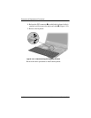
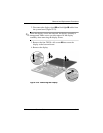
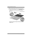
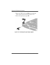
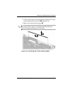
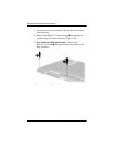
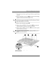
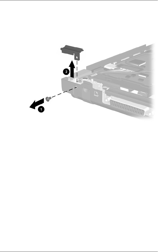
3. Remove the TM2.0 × 6.0 screw 1 that secures the right
display support to the base enclosure (Figure 5-25).
4. Remove the right display support 2.
Figure 5-25. Removing the Right Display Support