


9131
Rev. M
3.1.3.1 Mechanical Installation Cont'd
( ) 3. Remove the electrical assembly from the enclosure by
loosening and removing the mounting hardware from the
four corners of the base plate panel.
( ) 4. The electrical assembly can now be placed in the shipping
carton for protection.
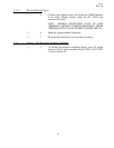
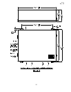
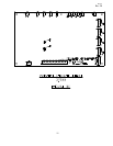
( ) 5. Proceed to mount the empty enclosure in the desired fashion.
Recommended conduit hole locations are shown on Figure 3.
( ) 6. Remove all dirt and foreign material from the enclosure, then
re-install the electrical assembly in the enclosure after
completing the mounting and conduit connector installation.
3.1.3.2 Electrical Wiring
( ) 1. Connect the ground conductor to the ground lug located in
the lower left hand corner of the base plate.
( ) 2. Connect the remote control leads to 31955 TB1 terminals as
indicated.
L - 120 VAC hot lead (Input for Option -2 is
LN - 120 VAC Neutral to "H" terminals on Step-
down Transformer)
CR - Remote Control Common
C1 - Remote Control Circuit 1
C2 - Remote Control Circuit 2
C3 - Remote Control Circuit 3 for 84700-3 & -4
C4 - Remote Control Circuit 4 for 84700-4
Note: 31955 TB1 is removable for ease of installation.
( ) 3. Connect the CCR control power to 31955 TB1 terminals as
indicated:
CC1 - Control Power Feed from Regulator
CC2 - Control Load to Tower
See page 7A.
( ) 4. Connect the output of the CCR to terminals R1 and R2, in
the high voltage section, using the #12 AWG ring terminals
provided.
7