


9131
Rev. M
SECTION 6
OPTIONS
6.1 SCOPE
The following listing provides parts ordering data and customer installation data.
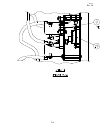
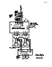
6.2 OPTION -2
The part number for the 220VAC transformer is 10047-1444. Customer primary
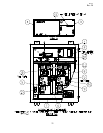
input connections are at points H1 and H4 on the transformer; see Figures 6-2A and
6-2B. See Figure 5-1 or 5-2 for transformer location.
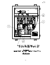
6.3 Option -3
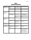
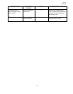
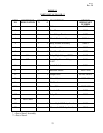
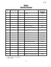
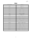
Item 4 circuit card, see Figure 5-1 or 5-2 for location, changes with Option -3. See
Table 6-1 for circuit card part number variations. See Figure 6-3,-4,-11 for external
remote control connections.
6.4 Option -4
Item 4 circuit card, see Figure 5-1 or 5-2 for location, changes with Option -4. See
Table 6-1 for circuit card part number variations. See Figure 6-3,-4,-11 for external
remote control connections.
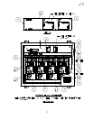
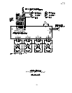
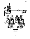
6.5 Option -5
The part number for the current sensing circuit card is 31978-1 for 1 loop sensing
(84700-1 or -3, 1 required) and 31978-2 for 2 loop sensing (84700-2 or -4; -4
requires 2 cards). Item 5 relay module P/N is 30848-3. Item 14 relay module P/N is
30848-6. See Figure 5-1 or 5-2 for parts locations. See Figure 6-5A or 6-5-B for
wiring diagram.
6.6 Option -6
Same as Option -5, except Item 5 P/N is 30848-2 and Item 14 P/N is 30848-5.
6.7 Option -7
Discontinued.
6.8 Option -8
Item 4 circuit card, see Figure 5-1 or 5-2 for location, changes with option -8. See
Table 6-1 for circuit card part number variations.
25