


9131
Rev. M
6.9 Option -9
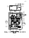
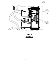
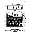
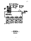
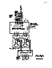
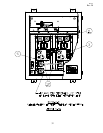
Item 11 P/N is 10047-1878. Item 12 P/N is 46-192-5X/D-8. The part number for the
interlock switch harness is 31985-1. Item 5 P/N is the same as for standard 84700-2
module, except option -9 labeling required and, if present, remove lead with tag
"THIS JUMPER TO BE REMOVED ONLY WHEN CONNECTING LOAD TO
THESE TERMINALS". See Figure 6-9A for parts location. See Figure 6-9B for
wiring diagram.
6.10 Option -10
Cabinet P/N is 30834 for 84700-1 or -2 and 30835 for 84700-3 or -4.
6.11 Option -11
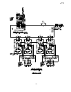
Item 4 circuit card, see Figure 5-1 or 5-2 for location, changes with Option -11. See
Table 6-1 for circuit card part number variations. See Figure 6-3,-4,-11 for external
remote control connections.
6.12 Option -12
Item 14 P/N is 10047-2276 (except when used with Option -9; use Option -9 Item
14). The actuator extender P/N is 10037-573. Item 10 P/N for 84700-1 or -2 is
31986 and 31987 for 84700-3 or -4. See Figure 5-1 or 5-2 for parts location.
6.13 Option -13
Cabinet P/N is 30834-1 for 84700-1 or -2 and 30835-1 for 84700-3 or -4.
6.14 OPTION -14
Circuit Selector Switch without the Cabinet.
6.15 OPTION -15
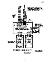
The part number for the 480VAC transformer is 10047-1444. Customer primary
input connections are at points H1 and H4 on the transformer; see Figures 6-2A and
6-2B. See Figure 5-1 or 5-2 for transformer location.
26