


9131
Rev. M
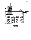
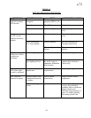
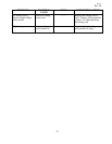
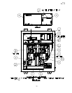
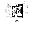
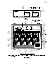
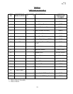
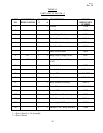
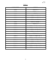
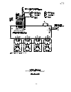
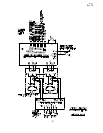
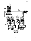
TABLE 5-2
PARTS LIST, 84700-3 OR -4
ITEM
NO
REFERENCE
DESIGNATION
QUANTITY
-3 -4
DESCRIPTION CROUSE
HINDS PART
NUMBER
1 1 1 Cabinet 31530
2 1 1 Base Plate 30859
3 1 1 Low Voltage Panel 31974
4 1 1 Circuit Card assembly 31955-2
5 2 2 Relay Module Assembly 30848-1
6 1 1 Dead Front Plate 30833
7 1 1 Dead Front Bracket 30829
*8 K1 3 4 Relay, High Voltage, SPNC 34197
*9 K2 3 4 Assembly, Vacuum Relay,
L-847
34196
10 1 1 Switch Label 31975
11 1 1 Interlock Switch 10047-1616
12 2 3 Jumper Wire 46-245-5X/D-4
13 1 1 Ground Stud 10053-184
14 1 2 Relay Module Assembly
30848-4
**15 1 1 Fuse, 3.0A 10047-1591
16 1 1 Interlock Harness 31985
*17 2 2 Relay Harness (Item 5 only) 30853
*18 1 2 Relay Harness (Item 14 only) 30853-1
*19 3 4 Assembly,L-847 Relay Interface 34195
*20 3 4 Harness, L-847 Relay Interface 32849
* = Part of Item 5 or 14 Assembly
** = Part of Item 4
24