


M-LIB3 Low Impedance Bus Differential Relay
2
INDEX
1 General utilization and commissioning directions_______________________________________________________ 3
1.1 Storage and transportation______________________________________________________________________ 3
1.2 Installation___________________________________________________________________________________ 3
1.3 Electrical connection___________________________________________________________________________ 3
1.4 Measuring inputs and power supply_______________________________________________________________ 3
1.5 Outputs loading_______________________________________________________________________________ 3
1.6 Protection earthing_____________________________________________________________________________ 3
1.7 Setting and calibration__________________________________________________________________________ 3
1.8 Safety protection______________________________________________________________________________ 3
1.9 Handling____________________________________________________________________________________ 3
1.10 Maintenance_________________________________________________________________________________ 4
1.11 Fault detection and repair_______________________________________________________________________ 4
2 General characteristics and operation________________________________________________________________ 5
2.1 Modular Low Impedance Bus Bar Protection M-LIB3__________________________________________________ 5
2.2 Main features_________________________________________________________________________________ 5
2.3 Component Modules___________________________________________________________________________ 5
2.3.1 M-BF3 = Income/Feeder Breaker input module (SCE1577)________________________________________ 5
2.3.2 M-BC3 = Bus coupler / sectionalizer module (SCE1578)__________________________________________ 6
2.3.3 M-LID3 =Numerical biased protection relay____________________________________________________ 6
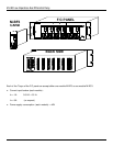
2.4 F/C Rack Panel_______________________________________________________________________________ 7
2.5 Accessoeries_________________________________________________________________________________ 8
2.5.1 CF1- Cable with female plug________________________________________________________________ 8
2.5.2 CFM – Interconnection cable with Male an Female plugs__________________________________________ 9
2.6 Technical Data________________________________________________________________________________ 10
2.7 Current Transformer Requirements________________________________________________________________ 10
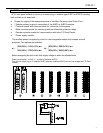
3 Apparatus Configuration____________________________________________________________________________ 11
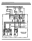
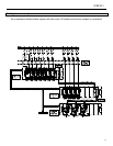
3.1 Single-Line Diagram____________________________________________________________________________12
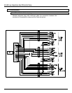
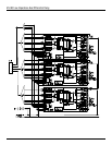
3.2 Application example____________________________________________________________________________ 13
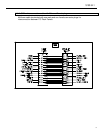
4 Feeder Input Module M-BF3__________________________________________________________________________ 15
4.1 Wiring diagram M-BF3__________________________________________________________________________ 17
5 Feeder Input Module M-BC3__________________________________________________________________________18
5.1 Wiring diagram M-BC3__________________________________________________________________________20
6 Digital Low Impedance Differential Protection Relay M-LID3_______________________________________________ 21
6.1 General Characteristic__________________________________________________________________________ 22
6.2 Power Supply_________________________________________________________________________________ 22
6.3 Measurements Acquisition and Operation Principle____________________________________________________22
6.4 Operation of the Biased Differential elements________________________________________________________ 23
6.5 Control and Measurements______________________________________________________________________ 25
6.6 Measurements Acquisition and Operation Principle___________________________________________________ 26
6.7 Output relays_________________________________________________________________________________ 27
6.8 Serial Communication__________________________________________________________________________ 27
6.9 Oscillography Records__________________________________________________________________________ 27
6.10 Digital Input__________________________________________________________________________________ 27
6.11 Test________________________________________________________________________________________ 28
6.12 Keyboard and Display Operation__________________________________________________________________ 28
6.13 Reading of Measurements and Recorded Parameters_________________________________________________29
6.13.1 Actual Measurements (ACT. MEAS)__________________________________________________________ 29
6.13.2 Max Value (MAX.VAL)_____________________________________________________________________ 29
6.13.3 Last Trip (LASTTRIP)______________________________________________________________________ 29
6.13.4 Trip Number (TRIP NUM)___________________________________________________________________29
6.14 Reading of Programmed Setting and Relay’s Configuration_____________________________________________ 30
6.15 Programming_________________________________________________________________________________ 30
6.15.1 Programming of functions settings____________________________________________________________ 30
6.15.2 Programming the configuration of output relays__________________________________________________31
6.16 Manual and Automatic Test Operation______________________________________________________________32
6.16.1 Mode “TESTPROG ” subprogram “W/O TRIP ”__________________________________________________ 32
6.16.2 Mode “TESTPROG ” subprogram “WithTRIP ”___________________________________________________32
6.17 Maintenence__________________________________________________________________________________32
6.18 Clock and Calendar____________________________________________________________________________ 33
6.18.1 Clock synchronization______________________________________________________________________33
6.18.2 Date and time setting______________________________________________________________________ 33
6.18.3 Time resolution___________________________________________________________________________ 33
6.18.4 Operation during power off__________________________________________________________________ 33
6.18.5 Time tolerance___________________________________________________________________________ 33
6.19 Wiring Diagram M-LID3_________________________________________________________________________ 34
6.20 Electrical Characteristics________________________________________________________________________ 35