


S150-34-1
31
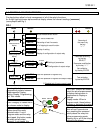
6.15.2 PROGRAMMING THE CONFIGURATION OF OUTPUT RELAYS
Mode PROG menu F→RELAY (Production standard settings here under shown).
The key "+" operates as cursor; it moves through the numbers corresponding to the four programmable relays
in the sequence 1,2,3,4,(1= relay R1, etc.) and makes start flashing the information actually present in the
digit. The information present in the digit can be either the number of the relay (if this was already associated
to the function actually on programming) or a dot (-) if the relay was not yet addressed.
The key "-" changes the existing status from the dot to the relay number or vice versa.
After having programmed all four relays, press “ ENTER “ to validate the programmed
configuration.
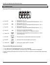
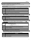
Display Description
Is 1---
Bias Differential element operates relay R1 eventually plus R2, R3, R4 as programmed
(one or more)
Ids -2--
Un-biased differential element operates relay R2, R3, R4 as programmed
Isv --3-
Time delayed CT supervision element operates relay R2, R3, R4 as programmed
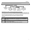
FRes: Aut.
Reset of output relays after tripping is:
Aut. = Automatic Man. = Manually key Enter /Reset or via serial bus
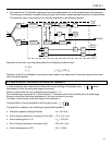
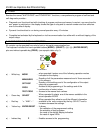
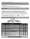
d> - 2 - 4
This dash means
that output relay
number 1 is not
assigned to this
element
This is the name
of protective
element
The number 2
means that
output relay 2
will operate
when this
This dash
means that
output relay
number 3 is not
assigned to this
element
The number 4
means that output
relay 4 will operate
when this element
trips