


S150-34-1
27
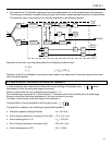
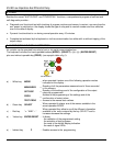
6.7 OUTPUT RELAYS
Five output relays are available (R1, R2, R3, R4, R5)
q The relays R1,R2,R3,R4 are normally de-energized (energized on trip): these output relays are user
programmable and any of they can be associated to any of the M-LID3's functions.
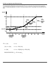
Any relay associated to of any function picks-up as soon as the measured input value gets into the
operation zone.
The reset after tripping of the relays (when tripping cause has been cleared) can be programmed as
Manual or Automatic (Variable FRes=Man/Aut).
FRes = Aut : Automatic Reset as soon as pick-up cause has been cleared.
FRes = Man : Reset by ENT/RESET KEY on relay’s front or via serial port
q The relay R5, normally energized, is not programmable and is de-energized on:
♦ Internal fault.
♦ Power supply failure.
♦ During the programming.
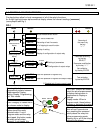
6.8 SERIAL COMMUNICATION (Optional: see relevant instruction manual)
The relays fitted with the serial communication option can be connected via a cable bus or
(with proper adapters) a fiber optic bus for interfacing with a Personal Computer
Via the communication bus all settings and commands available from relay's keyboard can be operated from
the computer and vice versa all information available at relay's level can be received at computer's level. The
transmission standard is RS485 (converter 485/232 available) with ModBus/Jbus protocol.
Each relay is identified by its programmable address code (NodeAd) and can be called from the P.C. fitted
with a WINDOWS (95/98 or later) program driven by an application program supplied by Cooper Power
Systems or one developed by the user.
6.9 OSCILLOGRAPHY RECORDS
The relay continuously records in a buffer the samples of the three phase differential currents.
The buffer contains samples for approximately 16 periods.
Recording is stopped approximately 8 periods after a trigger signal is received and the content of the buffer is
stored into memory.
Therefore in the memory are stored the wave forms for 8 cycles before and 8 cycles after the trigger
occurs.
The trigger can be operated either internally on tripping of any function programmed I
dS
, I
S
, or externally by
activation of the REMOTE TRIGGER digital input.
Selection between the two modes is made by programming the variable TRG = EXT, I
dS
, I
S
,
The last two oscillography records are stored; a third record replaces the first of the two records.
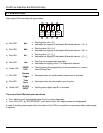
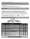
6.10 DIGITAL INPUTS
Three inputs active when the relevant terminals are shorted are provided:
q
TS
terminals 1 - 2 : For time synchronization
q
BI
terminals 1 - 3 : For trip lock-out
q
RT
terminals 1 - 14 : External trigger for oscillography records