22
SPECIFICATIONS (Continued)
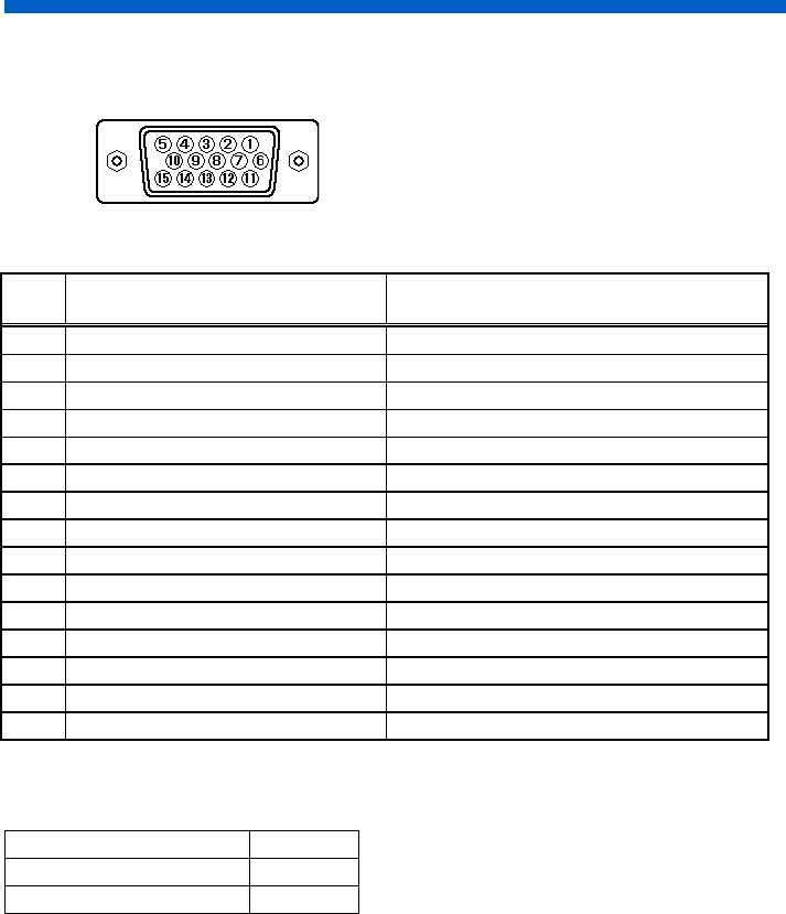
Pin Assignment
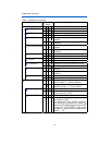
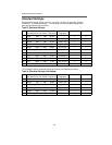
Signal Input Connector of the Monitor
Table 7. Pin Assignment
Pin
No.
Input 1 Input 2
1
Red Video Red Video
2
Green Video Green Video
3
Blue Video Blue Video
4
No pin No pin
5
No connection No connection
6
Red Ground Red Ground
7
Green Ground Green Ground
8
Blue Ground Blue Ground
9
No connection No connection
10
Ground Ground
11
No connection No connection
12
Bi-directional Data [SDA] No connection
13
H-Sync. (or H/V) H-Sync. (or H/V)
14
V-Sync. [VCLK] V-Sync.
15
Data Clock [SCL] No connection
If the graphics board supplies more than one type of sync. signal, the sync. signal type
will be automatically selected by the monitor, with the priority shown in the following table.
Sync. Signal Type Priority
H, V Separate Sync. 1
H/V Composite Sync. 2


