


DIN Rail High-Voltage Switch Crestron DIN-8SW8
Connectors, Controls & Indicators (Continued)
# CONNECTORS*,
CONTROLS & INDICATORS
DESCRIPTION
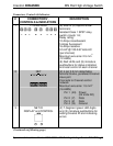
4 SETUP
(LED and BUTTON)
(1) Red LED and (1) recessed
miniature pushbutton for enabling
setup mode and touch-settable ID
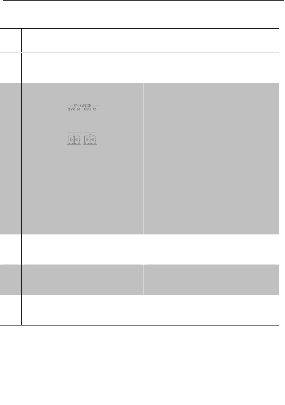
5 OVERRIDE
with LEDs and BUTTON
(2) 2-pin 3.5 mm detachable
terminal blocks, paralleled;
Maximum wire size: 1.5 mm
2
(16 AWG)
Sensing input for external
low-voltage contact closure;
Activates Override mode when a
closure is present;
Minimum closure rating:
10 mA (per module) at 24 Volts
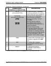
(1) Red LED and (1) miniature
pushbutton for enabling Override
mode and saving override presets.
For more information, refer to
“Operation” which starts on page
21.
6 PWR (1) Green LED, illuminates when
DC power is applied to the NET
port
7 NET (1) Yellow LED, indicates
communication with the control
processor
8 RESET (1) Recessed miniature
pushbutton, resets internal
processor
* Interface connectors for NET and OVERRIDE ports are provided with the unit.
8 • DIN Rail High-Voltage Switch: DIN-8SW8 Operations & Installation Guide – DOC. 6666A