


Crestron DIN-HUB DIN Rail Cresnet
®
Distribution Hub
Connectors, Controls & Indicators (Continued)
# CONNECTORS
1
,
CONTROLS &
INDICATORS
DESCRIPTION
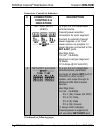
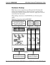
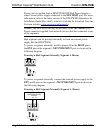
2 NET HOST and LEDs
(Continued)
(1) Yellow LED indicates
Cresnet bus activity at either
NET HOST port
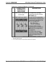
3 NET A/B/C and LEDs
2
(6) 4-pin 3.5 mm detachable
terminal blocks comprising (2)
Cresnet ports (paralleled) per
each of (3) segments
Max Wire Size:
1.5 mm
2
(16 AWG)
(3) Green LEDs indicate
Cresnet power is available at
NET ports of corresponding
hub segment
(3) Yellow LEDs indicate
Cresnet bus activity at NET
ports of corresponding hub
segment
1. Interface connectors for NET HOST, NET PWR INPUT, and NET ports are
provided with the unit.
2. Y, Z, and G terminals are paralleled within each segment.
Operations & Installation Guide – DOC. 6671A DIN Rail Cresnet Hub: DIN-HUB • 7