


DIN Rail Cresnet
®
Distribution Hub Crestron DIN-HUB
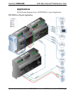
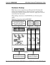
Three-Segment Cresnet Hub
Cresnet is the communications backbone for Crestron lighting modules,
wall box dimmers, shade controllers, thermostats, keypads, touchpanels,
and many other devices. This flexible 4-wire bus normally supports
approximately 20 Cresnet devices without requiring a hub. Larger
systems are easily enabled by adding the DIN-HUB. The DIN-HUB
features three isolated Cresnet segments, each supporting an additional
20 devices, allowing for systems of approximately 80 devices total
(including the “host” segment). More hubs may be added to allow up to a
maximum potential of 252 devices.*
* The actual number of possible devices per segment and per network may vary
depending upon the amount of data traffic, the length and geometry of network
wiring, and the power requirements of every device. A general rule of thumb
suggests approximately 20 devices, an aggregate of 914 meters (3000 feet) of
cable, and up to a 75 Watt load per segment (wiring and devices permitting). In
any case, 252 is the maximum number of possible devices on a complete Cresnet
network. Contact Crestron True Blue Support
(www.crestron.com/true_blue_support) for further design assistance.
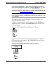
Cresnet Power Distribution
In addition to data, Cresnet carries 24 Volts DC for powering the devices
connected to it. The DIN-HUB provides an easy way to manage the
distribution of power for a complete Cresnet network. Each segment can
be configured to receive its power from the “host” power source or from
another power supply. Separate power supplies may be dedicated to each
segment, or a single supply can be shared amongst multiple segments as
needed. Each segment supports up to 75 Watts.
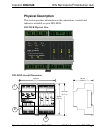
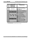
DIN Rail Installation
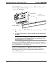
The DIN-HUB is designed to snap onto a standard DIN rail for
installation in a wall mount enclosure or mounted on a wall panel. Wiring
connections are made using detachable screw terminals positioned along
the top and bottom, clearly accessible from the front for easy installation
and servicing. Diagnostic indicators are positioned on the center front
panel. When installed in an enclosure utilizing 45 mm cutouts, the
DIN-HUB’s front panel stays visible while the connections are
concealed.
2 • DIN Rail Cresnet Hub: DIN-HUB Operations & Installation Guide – DOC. 6671A