


Power Switching Cabinet GLPX-HSW-FT CRESTRON GREEN LIGHT
®
EXPRESS
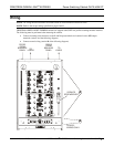
NET Port Wiring
When wiring the supplied NET connectors for connection to a Crestron control system or other device on the
Cresnet network, use Crestron certified wire such as CRESNET-NP or CRESNET-P.
To ensure optimum performance over the full range of your installation topology, use Crestron certified wire.
Failure to do so may incur additional charges if support is required to identify performance deficiencies because
When daisy-chaining connections between NET ports, strip the ends of the wires carefully to avoid nicking the
the ends of the wires that share a pin on the network connector, insert the connection
s e retai epeat the procedure for the other three conductors.
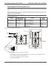
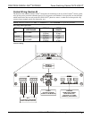
WER Port Wiring
odule in the cabinet receives power via the line voltage connected to channel 1. In the event that line
is un module can recei a a backup ge supply. Low voltage (24 VDC)
ay be suppl he modules eithe a the NE externally via a Cresnet power
WER port.
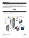
To power the modules from the NET port, in per from th n on the supplied POWER
he EXT pin on the POWER connector as shown in the following diagram.
Providing Cresnet Power Via The Net Port
of using improper wire.
conductors. Twist together
into the Cre net connector, tighten th ning screw. R
PO
Each m
voltage
power m
available, the
ied to t
ve power vi
r internally vi
low volta
T port or
supply connected to the PO
stall a jum e INT pi
connector to t
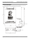
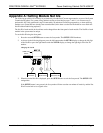
To power the modules externally from a Cresnet 24 VDC power supply, connect the external power supply to
the EXT and G pins on the POWER supplied connector as shown in the following diagram.
Providing Cresnet Power Via Dedicated Power Supply
CRESTRON 24 VDC
POWER SUPPLY
G 24
When properly connected and receiving 24 VDC power, the green LED next to the MODULES port will light.
OVERRIDE Port Wiring
When a connection is applied between the override terminals, the modules will enter override mode. The
Crestron GLS-PLS-120/277 phase-loss sensor or any device that provides a dry contact closure can be
connected to the supplied OVERRIDE connector on the bottom of the cabinet.
10 • GREEN LIGHT
®
EXPRESS Power Switching Cabinet GLPX-HSW-FT Installation Guide – DOC. 6888B