


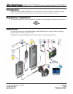
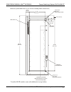

Power Switching Cabinet GLPX-HSW-FT CRESTRON GREEN LIGHT
®
EXPRESS
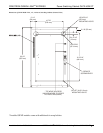
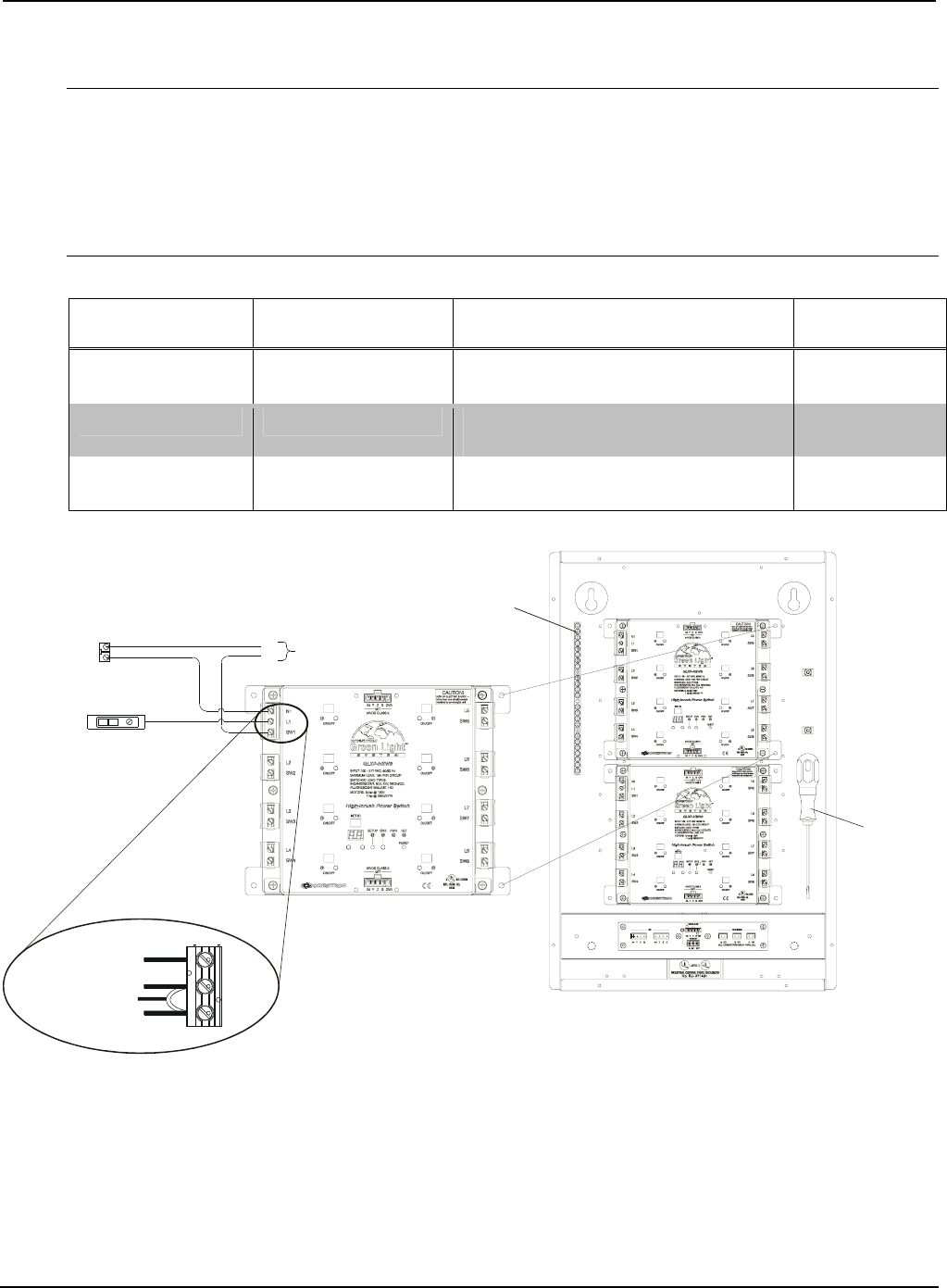
Feed-Through and Load Wiring (Section A)
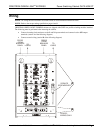
ION: Bypass jumpers are provided on each output to allow testing and to protect the modules during CAUT
installation. The jumper shorts the L and SW terminals so that the load circuit is energized when
is on.
the branch breaker
NOTE: Do not remove the bypass jumper until all feed and load wiring has been completed, and the circuits
have been tested for electrical faults.
NOTE: Use copper conductors only – rated 75°C.
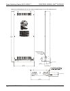
Wire
ORQUE STRIP
LENGTH
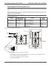
Gauge and Torque Values
TERMINAL CONNECTOR MAX
WIRE RANGE
T
L AND N INPUTS 26-10 AWG 5.31 lb-in (0.6 Nm) to
7.08 lb-in (0.8 Nm) max
3/8”
(9 mm)
SW OUTPUTS 26-10 AWG 5.31 lb-in (0.6 Nm) to
7.08 lb-in (0.8 Nm) max
3/8”
(9 mm)
GROUND LUG 14-4 AWG 25-45 lb-in
(2.8-5.1 Nm)
3/4"
(19 mm)
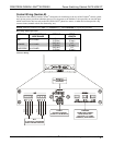
Load Wiring for GLXP-HSW8 and GLXP-HSW12
TO NEUTRAL*
TO BRANCH BREAKER
TO LOAD
JUMPER
L
CIRCUIT BREAKER (20A MAX)
NEUTRAL
BUS
TO LOADS
N
L
GROUND LUG
N1
L1
SW1
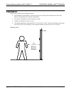
SERVICE
SCREWDRIVER
* A single NEUTRAL connection is required for each module.
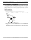
1. Test the circuit for electrical faults by turning on each circuit breaker, checking that the breakers do not
trip, and that power is delivered to the proper loads.
2. Turn off the circuit breaker(s) and remove all jumpers.
3. Turn on the circuit breakers.
8 • GREEN LIGHT
®
EXPRESS Power Switching Cabinet GLPX-HSW-FT Installation Guide – DOC. 6888B