


CRESTRON GREEN LIGHT
®
EXPRESS Power Switching Cabinet GLPX-HSW-FT
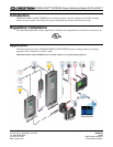
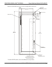
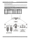
Control Wiring (Section B)
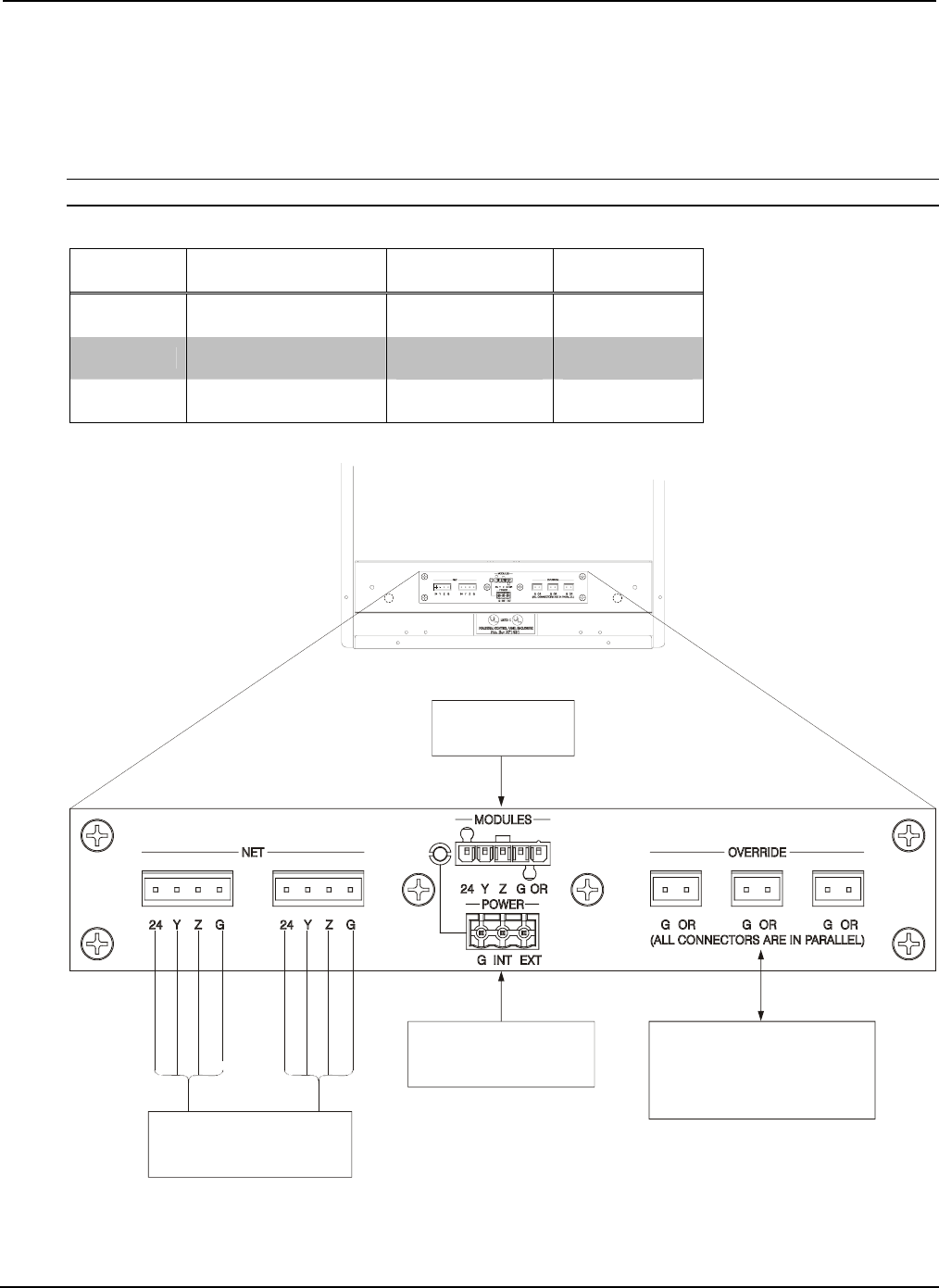
The bottom of the cabinet contains Cresnet connections for interfacing to the rest of the Crestron control system
and a power port to provide an alternate source of 24 volt power to the modules. It also provides an override input
which can be tied to devices such as the GLS-PLS-120/277 phase-loss sensor, or other devices that provide a dry
contact
® ®
,
closure (manual switch, fire alarm relay, etc.).
NOTE: Interface connectors for NET (x2), POWER (x1), and OVERRIDE (x3) ports are provided.
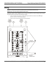
Wire Gauge and Torque Values
TERMINAL CONNECTOR MAX TORQUE STRIP
WIRE RANGE LENGTH
NET -12 AW
43 lb-in
.5 Nm)
26 G
4.
(0
1/4”
(6 mm)
POWER 26-12 AWG
4.43 lb-in
(0.5 Nm)
1/4”
(6 mm)
OVERRIDE 26-12 AWG
4.4
(0.5 Nm)
3 lb-in 1/4”
(6 mm)
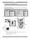
Connector Wiring
RED
WHITE
BLUE
BLACK
NET:
TO CONTROL SYSTEM AND
OTHER CRESNET DEVICES
RED
WHITE
BLUE
BLACK
POWER:
PROVIDES CRESNET
LESPOWER TO THE MODU
OVERRIDE:
FROM OTHER CABINET;
FROM ALARM, ETC.
(OPTIONAL); TO OTHER
CABINET(S) IF NECESSARY
MODULES:
TO GLXP MODULES
(PREWIRED)
Installation Guide – DOC. 6888B GREEN LIGHT
®
EXPRESS Power Switching Cabinet GLPX-HSW-FT • 9