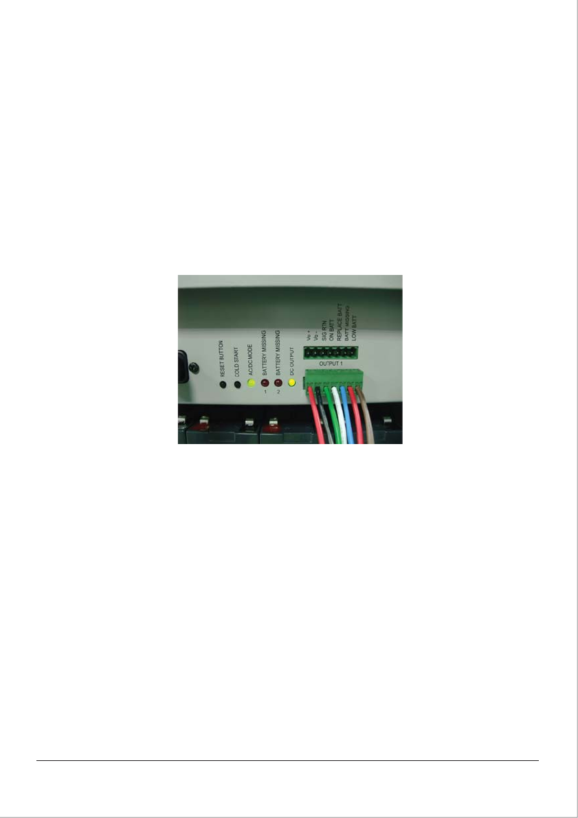
4.8 ONT Alarm Connections
1. Route the 7-wire cable back from the ONT enclosure to the UPS.
2. Remove any convenient 3/4” knock-out of the UPS enclosure.
3. Install a strain relief in the knock-out hole.
4. Route the power cable up through the strain relief.
5. Trim the cable to the desired length and strip back approximately 2” of the jacket.
6. Using a jeweler’s standard blade screwdriver, attach the wires to the connector referencing the
ONT pin-out information.
7. Tighten the strain relief around the power cord.
Note: Be certain to utilize environmentally sealed strain-reliefs, cordgrips, or conduit at the cable
exit point.
Note: Output wires should be installed in accordance with Article 800 of ANSI/NFPA 70.
5 OPERATION
5.1 Start-Up
1. Supply AC power.
2. During initial start-up, observe the following:
a. The AC/DC Mode LED illuminates (Green). The UPS is running on AC (utility) power and the
batteries are charging.
b. The DC Output LED illuminates (Green). The UPS is outputting DC power to the ONT.
3. Route and secure the cables to the wire management brackets.
4. Close and latch the front cover of the UPS.
© 2010 CyberPower Systems (USA), Inc. All Trademarks are property of their owners. Page: 13 of 17
Figure 16: LED’s and ONT Alarm Connections


