


CY7C0430BV
CY7C0430CV
Document #: 38-06027 Rev. *B Page 21 of 37
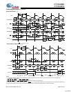
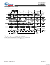
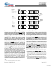
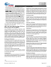
Counter Interrupt
[37, 38, 39]
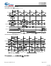
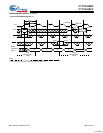
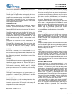
Mailbox Interrupt Timing
[40, 41, 42, 43, 44]
Notes:
37.CE
0
= OE = LB = UB = V
IL
; CE
1
= R/W = CNTRST = MRST = CNTRD = MKRD = V
IH
.
38.CNTINT
is always driven.
39.CNTINC
goes LOW as the counter address masked portion is incremented from xx7Fh to xx00h. The “x” is “Don’t Care.”
40.CE
0
= OE = LB = UB = CNTLD =V
IL
; CE
1
= CNTRST = MRST = CNTRD = CNTINC = MKRD = MKLD =V
IH
.
41.Address “FFFE” is the mailbox location for Port 2.
42.Port 1 is configured for Write operation, and Port 2 is configured for Read operation.
43.Port 1 and Port 2 are used for simplicity. All four ports can write to or read from any mailbox.
44.Interrupt flag is set with respect to the rising edge of the write clock, and is reset with respect to the rising edge of the read clock.
Switching Waveforms (continued)
t
SMLD
t
HMLD
t
SCLD
t
HCLD
t
CH2
t
CL2
t
CYC2
CLK
MKLD
CNTLD
A
n
xx7Eh
INTERNAL
ADDRESS
xx7Fh
xx00h
xx7Dh
EXTERNAL
ADDRESS
t
SCINC
t
HCINC
CNTINC
COUNTER
007Fh
xx7Dh
xx00h
CNTINT
t
SCINT
t
RCINT
t
CH2
t
CL2
t
CYC2
CLK
P1
t
CH2
t
CL2
t
CYC2
CLK
P2
FFFE
t
SA
t
HA
A
n+3
A
n
A
n+1
A
n+2
PORT-1
ADDRESS
A
m
A
m+4
A
m+1
FFFE
A
m+3
PORT-2
ADDRESS
INT
P2
t
SA
t
HA
t
SINT
t
RINT
[+] Feedback