


CY8C24223A, CY8C24423A
Document Number: 3-12029 Rev. *E Page 3 of 31
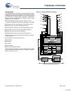
Analog System
The Analog System is composed of six configurable blocks, each
comprised of an opamp circuit allowing the creation of complex
analog signal flows. Analog peripherals are very flexible and can
be customized to support specific application requirements.
Some of the more common PSoC analog functions (most
available as user modules) are:
■ Analog-to-digital converters (up to two, with 6 to 14-bit
resolution, selectable as Incremental, Delta Sigma, and SAR)
■ Filters (two and four pole band-pass, low-pass, and notch)
■ Amplifiers (up to two, with selectable gain to 48x)
■ Instrumentation amplifiers (one with selectable gain to 93x)
■ Comparators (up to two, with 16 selectable thresholds)
■ DACs (up to two, with 6 to 9-bit resolution)
■ Multiplying DACs (up to two, with 6 to 9-bit resolution)
■ High current output drivers (two with 30 mA drive as a PSoC
Core resource)
■ 1.3V reference (as a System Resource)
■ DTMF Dialer
■ Modulators
■ Correlators
■ Peak Detectors
■ Many other topologies possible
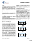
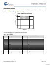
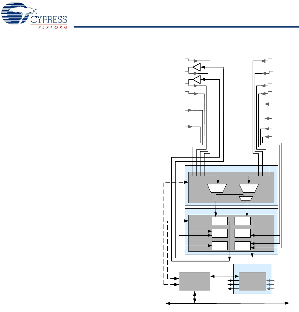
Analog blocks are arranged in a column of three, which includes
one CT (Continuous Time) and two SC (Switched Capacitor)
blocks, as shown in Figure 2.
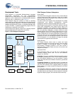
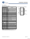
Figure 2. Analog System Block Diagram
ACB00 ACB01
Block Array
Array Input Configuration
ACI1[1:0]
ASD20
ACI0[1:0]
P0 [ 6]
P0 [ 4]
P0 [ 2]
P0 [ 0]
P2 [ 2]
P2 [ 0]
P2 [ 6]
P2 [ 4]
RefIn
AGNDIn
P0 [ 7 ]
P0 [ 5 ]
P0 [ 3 ]
P0 [ 1 ]
P2 [ 3 ]
P2 [ 1 ]
Re f e r e nce
Gene rator s
A GNDIn
Ref In
Bandgap
RefHi
RefLo
AGND
ASD11
ASC21
ASC10
Interface to
Digital System
M8C Interface (Address Bus, Data Bus, Etc.)
Analog Reference
[+] Feedback