


Back to Contents Page
System Board Assembly
DellStudio™1555ServiceManual
Removing the System Board Assembly
Replacing the System Board Assembly
The BIOS chip in the system board contains the Service Tag, which is also visible on a barcode label on the bottom of the computer. The replacement kit for the
system board includes media that provides a utility for transferring the Service Tag to the replacement system board.
Removing the System Board Assembly
1. Follow the instructions in Before You Begin.
2. Remove the palm rest (see Removing the Palm Rest).
3. Remove the optical drive (see Removing the Optical Drive).
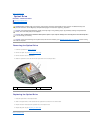
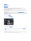
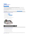
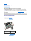
4. Disconnect the fan cable, AC adapter cable, USB cable, ExpressCard cables, and subwoofer cable from the respective system board connectors.
5. Remove the six screws that secure the system board to the computer base.
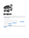
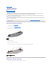
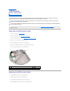
6. Remove the processor heat sink (see Removing the Processor Heat Sink).
7. Remove the processor (see Removing the Processor Module).
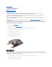
8. Remove the processor bracket from the system board.
WARNING: Before working inside your computer, read the safety information that shipped with your computer. For additional safety best
practices information, see the Regulatory Compliance Homepage at www.dell.com/regulatory_compliance.
CAUTION: To avoid electrostatic discharge, ground yourself by using a wrist grounding strap or by periodically touching an unpainted metal
surface (such as the back panel) on the computer.
CAUTION: Onlyacertifiedservicetechnicianshouldperformrepairsonyourcomputer.DamageduetoservicingthatisnotauthorizedbyDell™
is not covered by your warranty.
CAUTION: To help prevent damage to the system board, remove the main battery (see Before Working Inside Your Computer) before working
inside the computer.
1
fan cable connector
2
screws (6)
3
AC adapter cable connector
4
USB cable connector
5
ExpressCard cables
6
subwoofer cable connector
7
system board