


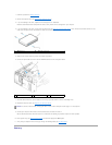
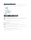
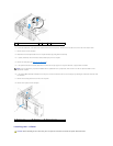

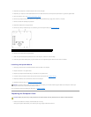

5. Use a long Phillips screwdriver to loosen the two captive screws, one on each side of the heat-sink assembly.
6. Rotate the heat-sink assembly towards the rear of the computer, and remove it from the computer.
7. Place the heat-sink assembly on its side in a safe place.
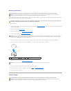
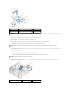
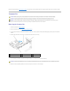
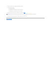
8. Disconnect the system fan cable from the system board.
9. Ensure that all cables have been removed from the routing clips on the top of the system fan assembly.
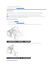
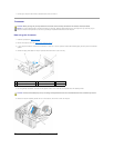
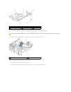
1
release tab
2
card retention mechanism
3
card retention door
4
heat sink captive screws (2)
CAUTION: The heat-sink assembly may be very hot during normal operation. Be sure that it has had sufficient time to cool before you touch it.
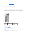
1
heat sink and fan shroud assembly
2
captive screw housing (2)