


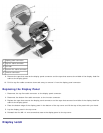

2. Remove the display assembly.
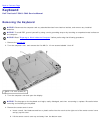
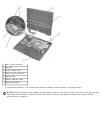
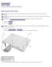
3. Use a plastic scribe to pry the six rubber screw covers out of the screw holes located on the front of the bezel.
4. Remove the six M2.5 x 5-mm screws located on the front of the bezel.
NOTICE: Carefully separate the bezel from the top cover to avoid damage to the bezel.
5. Starting at the bottom of the display panel (by the Dell™ logo), use your fingers to separate the bezel from the top
cover by lifting the inside of the bezel while pushing in on the outside.
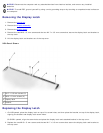
Removing the Display Panel
NOTICE: Disconnect the computer and any attached devices from electrical outlets, and remove any installed
batteries.
NOTICE: To avoid ESD, ground yourself by using a wrist grounding strap or by touching an unpainted metal surface on
the computer.
NOTICE: Read "Preparing to Work Inside the Computer" before performing the following procedure.
1. Remove the hard drive
.
2. Remove the display assembly
.
3. Remove the display bezel
.
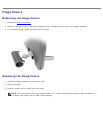
4. Remove the hinge covers
.
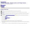
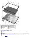
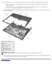
5. Remove the two M2 x 4-mm screws on the left side of the display panel and the two M2 x 4-mm screws on the right
side of the display panel.
NOTE: If you have a Hitachi display panel, remove the two M2 x 4-mm screws from the center of the left side of
the display panel.
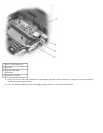
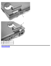
6. Remove the M2 x 4-mm screw that secures the display-feed flex cable through the black plastic flex-cable retention
bracket.
7. Lift from the top and rotate the display panel out of the top cover.
8. Disconnect the bottom flex cable connector from the inverter connector by pulling straight up on the attached pull-tab.