


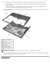


NOTICE: To ensure maximum cooling for the microprocessor, do not touch the heat transfer areas on the
microprocessor thermal cooling assembly. The oils in your skin reduce the heat transfer capability of the thermal pads.
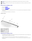
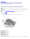
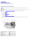
3. Remove the microprocessor thermal cooling assembly
.
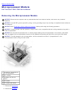
NOTICE: When removing the microprocessor module, pull the module straight up. Be careful not to bend the pins on
the microprocessor module.
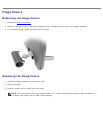
4. To loosen the ZIF socket, use a small, flat-blade screwdriver and rotate the ZIF-socket cam screw counter-clockwise
until it reaches the cam stop.
The ZIF-socket cam screw secures the microprocessor to the system board. Take note of the arrow on the ZIF-socket
cam screw.
5. Use a microprocessor extraction tool to remove the microprocessor module.
Replacing the Microprocessor Module
NOTICE: Ensure that the cam lock is in the fully open position before seating the microprocessor module. Seating the
microprocessor module properly in the ZIF socket does not require force.
NOTICE: A microprocessor module that is not properly seated can result in an intermittent connection, or permanent
damage to the microprocessor and ZIF socket.
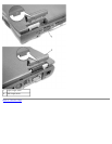
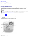
1. Align the pin-1 corner of the microprocessor module with the pin-1 corner of the ZIF socket, and insert the
microprocessor module.
NOTE: The pin-1 corner of the microprocessor module has a triangle that aligns with a triangle (or missing hole)
on the pin-1 corner of the ZIF socket.
NOTICE: You must position the microprocessor module correctly in the ZIF socket to avoid permanent damage to the
module and the socket.
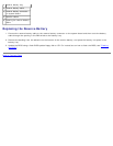
When the microprocessor module is correctly seated, all four corners are aligned at the same height. If one or more
corners of the module are higher than the others, the module is not seated correctly.
NOTICE: Do not touch the processor dienear the edges of the microprocessor module (on the substrate surrounding
the die) while turning the cam screw.
2. Press down on the edges of the microprocessor module and tighten the ZIF socket by turning the cam screw clockwise.
3. Install a new microprocessor thermal cooling assembly
.
NOTICE: To ensure proper thermal operation, always install a new, compatible thermal cooling assembly along with a
new microprocessor.
4. Update the BIOS using the flash BIOS update floppy disk or CD. For instructions on how to flash the BIOS, see
"Flashing the BIOS
."
Back to Contents Page