


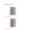
Power Supply Module Features And Indicators
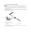
NOTE: Your storage array is shipped with two IEC C19 to C20 jumper cords. Connect the C19 plug
to the array's power supplies and the C20 plug to the power distribution unit (PDU) in the rack
cabinet.
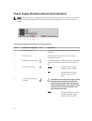
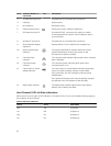
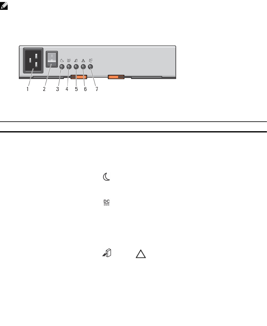
Figure 6. Power Supply Module Features and Status Indicators
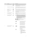
Item Indicator or Connector Icon Description
1 Power connector Connect the external power supply source to this
connector.
2 Power switch The power switch controls the power supply
output to the system.
3 Standby power indicator The standby power indicator lights green when the
system is in standby mode and the main power is
off.
4 DC power indicator
Green Indicates that DC output
voltage is within the limit.
Off Indicates that DC output
voltage is not within the
limit.
5 Service action allowed
indicator
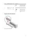
CAUTION: Remove the power supply module
from the system only if the service action
allowed indicator lights blue. Removing the
power supply module from the system when
the service action allowed indicator is off
may damage the system.
Blue Indicates that you can safely
remove the power supply
module from the system.
12