


Dell
™
Latitude™ E6400 XFR Service Manual
Page 55
instructions that shipped with your computer.
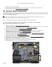
NOTICE: Ensure that any loose cables do not get caught beneath the system board.
1. Replace the card cage to the system board, before installing into the computer (see Replacing the Card Cage
).
2. Replace the gasket for the multi-mode display port.
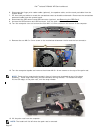
3. Place the left-edge (VGA connector and USB/E-SATA Port) of the system board into the base of the computer,
ensuring the system board fits through the VGA Panel, the gasket for the multi-mode HD video connector is
set properly, and the cable for the smartcard assembly is not interfering.
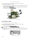
4. Connect the DC power cable to the bottom of the system board.
5. Lay the system board into place and push down on the back-right corner of the system board to connect it to
the I/O card.
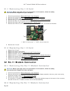
6. Replace the eight M2.5 x 5-mm screws to the system board.
7. Replace the two M2 x 3-mm screws for the card cage.
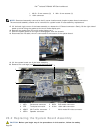
8. Route and connect the 1394 card cable to the connector on the system board. Press down on the flat area of
the cable to adhere it to the system board.
9. Install the Wi-Fi sniffer cable to the system board.
10. Connect the smartcard cable to the connector on the system board.
11. Replace the SIM card assembly (see Replacing the SIM Card Assembly
).
12. Replace the palm rest, keyboard, palm rest overlay and LED cover (see Replacing the Palm Rest
).
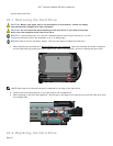
13. Replace the modular drive (see Replacing the Modular Drive
).
14. Replace the hard drive (see Replacing the Hard Drive).
15. Replace the processor, heatsink assembly, and fan (see Replacing the Processor Module
).
16. Replace the memory modules (see Replacing a Memory Module
).
17. Replace the mini-pci cards in the WPAN/UWB/FCM card slot, WLAN/WiMax card slot, and/or WWAN/FCM card
slot, if applicable (see Chapters 5, 6, 7 and 8
for replacement procedures).
18. Replace the coin cell battery (see Replacing the Coin Cell Battery
).
19. If you are installing a new system board, make a note of the number on the yellow label, located on the inside
of the bottom access panel. You will need this number when you first power on the computer for AMT
provisioning.
20. Replace the display assembly, LCD cable channel covers and bottom access panel (see Replacing the Display
Assembly).
21. Follow the procedures in After Working On Your Computer
.
22. At first power on, the AMT provisioning menu appears. See the instructions in the tech sheet that was
shipped with your replacement system board.
23. Enter the system setup program to update the BIOS on the new system board with the computer Service Tag.
For information on the system setup program, see the ™ Technology Guide on your computer or at
support.dell.com.
24. Run the SetXFR utility to allow the system board to operate as an E6400 XFR computer. See the instructions
in the tech sheet that was shipped with your replacement system board.
27 Card Cage
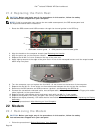
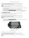
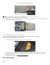
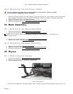
27.1 Removing the Card Cage
CAUTION: Before you begin any of the procedures in this section, follow the safety
instructions that shipped with your computer.
1. Follow the procedures in Before Working on Your Computer
.
2. Remove any PC-card or Express-card inserted.
3. Remove the system board (see Removing the System Board
).
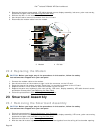
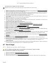
4. Slide the scribe under the cage then press outward to unhook the clips on both sides of the cage housing.