


Dell
™
Latitude™ E6400 XFR Service Manual
Page 62
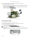
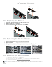
33.2 Replacing the DC Power Cable
CAUTION: Before you begin any of the procedures in this section, follow the safety
instructions that shipped with your computer.
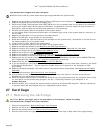
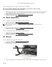
1. Place the DC power cable in the base assembly, aligning the guides on the connector sides with the base.
Once installed, press down firmly on top of the DC power connector to seal the adhesive to the base.
2. Route the DC power cable in the base assembly.
3. Replace the system board (see Replacing the System Board Assembly
).
4. Follow the procedures in After Working on Your Computer
.
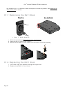
34 Base Assembly
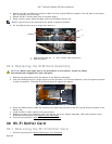
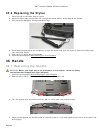
34.1 Removing the Base Assembly
1. Follow the procedures in Before Working on Your Computer.
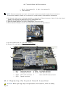
2. Remove the system board (see Removing the System Board Assembly
).
NOTE: Do not remove the mini-pci wireless or FCM cards, memory modules, or processor from
the system board.
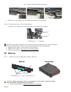
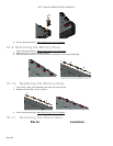
3. Remove the SIM card assembly (see Removing the SIM Card Assembly
).
4. Remove the modem (see Removing the Modem
).
34.2 Replacing the Base Assembly
1. Replace the modem (see Replacing the Modem).
2. Replace the system board (see Replacing the System Board Assembly
).
3. Follow the procedures in After Working on Your Computer
.
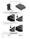
35 Stylus
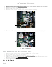
35.1 Removing the Stylus
1. Follow the procedures in Before Working on Your Computer.
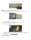
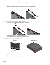
2. Remove the stylus from the stylus bay of the handle.
3. Close the display and turn the computer upside down.
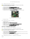
1 Tether anchor point
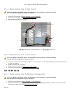
4. Run the stylus and tether through the tether loop, slide the lanyard from the loop then remove from unit.
1