


Working Inside Your Computer 5-5
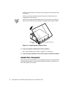
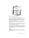
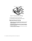
)LJXUH&RPSXWHU2ULHQWDWLRQ9LHZ
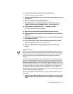
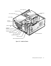
Figure 5-5 shows your computer with its cover removed. Refer to this illustration to
locate interior features and components discussed in this guide.
When you look inside your computer, note the
direct current (DC) power cables
com-
ing from the power supply. These cables supply power to the system board; to
internal diskette drives, hard-disk drives, and tape drives; and to certain expansion
cards that connect to external peripherals.
The flat ribbon cable in Figure 5-5 is typical of the
interface cables
for internal drives.
An interface cable connects a drive to a connector on the system board or on an
expansion card.
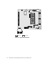
The
system board
—the large printed circuit board at the bottom of the chassis—holds
the computer’s control circuitry and other electronic components. Some hardware
options are installed directly onto the system board.
During an installation procedure, you may be required to change a
jumper
setting on
the system board and/or a jumper or
switch
setting on an expansion card or on a drive.
Jumpers and switches provide a convenient and reversible way of reconfiguring the
circuitry on a printed circuit board. For information on jumpers and switches, see the
following two subsections.
-XPSHUV
Jumpers are small blocks on a circuit board with two or more pins emerging from
them. Plastic plugs containing a wire fit down over the pins. The wire connects the
pins and creates a circuit.
right
side
left
side
front of computer
drive
bay
power
supply
internal
drive
cage
expansion-
card cage
back of computer
system
board