


6-2 Dell OptiPlex G1 Midsize Managed PC Reference and Installation Guide
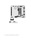
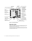
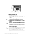
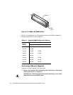
)LJXUH 6\VWHP% RDUG)HDWXUH V
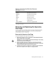
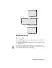
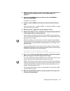
([SDQVLR Q&D UGV
Expansion cards are installed on the computer’s riser board (see Figure 6-3). The riser
board plugs into the RISER connector on the system board (see Figure 6-1) and is
considered an extension of the system board.
The system accommodates up to five expansion cards, which can be a mix of 32-bit
PCI expansion cards and 8- and 16-bit ISA expansion cards. (See Figure 6-2 for exam-
ples of ISA and PCI expansion cards.)
microprocessor
connector (SLOT1)
microprocessor
fan connector
(FAN)
video connector (MONITOR)
serial port 2
connector
(SERIAL2)
USB connectors (USB) (2)
parallel/serial port 1
connectors (stacked)
(PARALLEL/SERIAL1)
mouse/keyboard
connectors (stacked)
(MOUSE/KYBD)
video-memory
upgrade socket
(VIDEO_UPGRADE)
control panel connector (PANEL)
battery socket
(BATTERY)
optional
integrated NIC
connector (ENET)
riser board
connector (RISER)
system board jumpers
primary EIDE
interface connector
(IDE1) (pin-1 corner)
secondary EIDE
interface connector
(IDE2) (pin-1 corner)
front of
computer
diskette/tape drive interface connector
(DSKT) (pin-1 corner)
DIMM sockets (2)
(DIMM_A–DIMM_B)
main power input
connector (POWER_1)
3.3-V power input
connector (POWER_2)
ATI multimedia
connector (AMC)
CD-in connector (CD-IN)
chassis intrusion switch
connector (INTRUSION)
heat sink