


5-10 Dell OptiPlex G1 Midsize Managed PC Reference and Installation Guide
6\VWHP%RDUGDQG5LVHU%RDUG/DEHOV
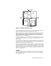
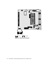
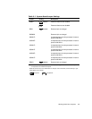
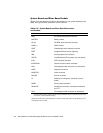
Table 5-2 lists the labels for connectors and sockets on your system board and riser
board, and it gives a brief description of their functions.
7DEOH6\VWHP%RDUGDQG5LVHU%RDUG&RQQHFWRUV
DQG6RFNHWV
&RQQHFWRURU6RFNHW 'HVFULSWLRQ
AMC ATI multimedia channel connector
BATTERY Battery socket
CD_IN CD-ROM audio interface connector
DIMM_
x
DIMM socket
DSKT Diskette/tape drive interface connector
ENET Integrated NIC connector (optional)
FAN Microprocessor fan connector
HDLED Hard-disk drive LED connector (on riser board)
IDE
n
EIDE interface connector
INTRUSION Chassis intrusion switch connector
ISA
n
*
ISA expansion-card connector (on riser board)
KYBD Keyboard connector
MONITOR Video connector
MOUSE Mouse connector
P1 Wakeup On LAN power connector (on riser
board)
PANEL Control panel connector
PARALLEL Parallel port connector; sometimes referred to
as
LPT1
PCI
n*
PCI expansion-card connector (on riser board)
* Connector ISA1 shares a single card-slot opening withPCI3. Only one connector at a time can
be used on a shared card-slot opening.
NOTE: For the full name of an abbreviation or acronym used in this table, see the Glossary in your
online
System User’s Guide
.