


vii
Audio Board . . . . . . . . . . . . . . . . . . . . . . . . . . . . . . . . . . . . . . . . . . . . . . 4-42
Main Board . . . . . . . . . . . . . . . . . . . . . . . . . . . . . . . . . . . . . . . . . . . . . . . 4-43
Cache Board . . . . . . . . . . . . . . . . . . . . . . . . . . . . . . . . . . . . . . . . . . . . . . 4-45
Index
Figures
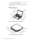
Figure 1-1. Front View of the Portable Computer . . . . . . . . . . . . . . . . . . . 1-2
Figure 1-2. Back View of the Portable Computer . . . . . . . . . . . . . . . . . . . 1-2
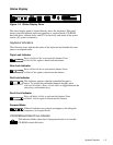
Figure 1-3. Status Display Panel. . . . . . . . . . . . . . . . . . . . . . . . . . . . . . . . . 1-3
Figure 4-1. Computer Orientation . . . . . . . . . . . . . . . . . . . . . . . . . . . . . . . 4-1
Figure 4-2. Screw Identification . . . . . . . . . . . . . . . . . . . . . . . . . . . . . . . . . 4-2
Figure 4-3. Main Battery Removal. . . . . . . . . . . . . . . . . . . . . . . . . . . . . . . 4-3
Figure 4-4. Hard-Disk Drive Removal . . . . . . . . . . . . . . . . . . . . . . . . . . . . 4-4
Figure 4-5. Options Bay Lock and Latch . . . . . . . . . . . . . . . . . . . . . . . . . . 4-4
Figure 4-6. Diskette Drive, Secondary Battery, or CD-ROM Removal. . . 4-5
Figure 4-7. PC Card Removal. . . . . . . . . . . . . . . . . . . . . . . . . . . . . . . . . . . 4-5
Figure 4-8. Releasing a ZIF Connector . . . . . . . . . . . . . . . . . . . . . . . . . . . 4-6
Figure 4-9. Exploded View—Computer. . . . . . . . . . . . . . . . . . . . . . . . . . . 4-7
Figure 4-10. Exploded View—LCD Assembly . . . . . . . . . . . . . . . . . . . . . . 4-8
Figure 4-11. Exploded View—Top Assembly . . . . . . . . . . . . . . . . . . . . . . . 4-9
Figure 4-12. Exploded View—Bottom Assembly . . . . . . . . . . . . . . . . . . . 4-10
Figure 4-13. Capacitor C146 (Location). . . . . . . . . . . . . . . . . . . . . . . . . . . 4-18
Figure 4-14. Hard-Disk Drive Disassembly . . . . . . . . . . . . . . . . . . . . . . . . 4-19
Figure 4-15. Diskette Drive Assembly . . . . . . . . . . . . . . . . . . . . . . . . . . . . 4-20
Figure 4-16. CD-ROM Assembly. . . . . . . . . . . . . . . . . . . . . . . . . . . . . . . . 4-21
Figure 4-17. Memory Module Removal. . . . . . . . . . . . . . . . . . . . . . . . . . . 4-22
Figure 4-18. LCD Assembly Removal . . . . . . . . . . . . . . . . . . . . . . . . . . . . 4-23
Figure 4-19. Front Bezel Removal . . . . . . . . . . . . . . . . . . . . . . . . . . . . . . . 4-24
Figure 4-20. LCD Panel Removal . . . . . . . . . . . . . . . . . . . . . . . . . . . . . . . 4-25
Figure 4-21. Inverter Board Removal. . . . . . . . . . . . . . . . . . . . . . . . . . . . . 4-26
Figure 4-22. LCD Assembly Latches Removal . . . . . . . . . . . . . . . . . . . . . 4-27
Figure 4-23. Power/Suspend Indicator Removal . . . . . . . . . . . . . . . . . . . . 4-28
Figure 4-24. Back Bezel Removal . . . . . . . . . . . . . . . . . . . . . . . . . . . . . . . 4-29
Figure 4-25. Keyboard Removal . . . . . . . . . . . . . . . . . . . . . . . . . . . . . . . . 4-30
Figure 4-26. Top Assembly Removal. . . . . . . . . . . . . . . . . . . . . . . . . . . . . 4-32
Figure 4-27. Speakers Removal . . . . . . . . . . . . . . . . . . . . . . . . . . . . . . . . . 4-34
Figure 4-28. Status Display Board Removal . . . . . . . . . . . . . . . . . . . . . . . 4-35