


support.dell.com Installing System Board Options 8-13
0'%
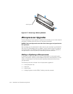
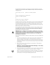
7. Unpack the new microprocessor.
If any of the pins on the microprocessor appear bent, see Chapter 10, “Getting
Help,” for instructions on obtaining technical assistance from Dell.
#+" , %
! !%+ !
!!
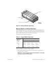
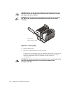
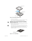
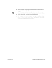
8. Align the pin-1 corner of the microprocessor chip (see Figure 8-11) with the pin-1
corner of the microprocessor socket.
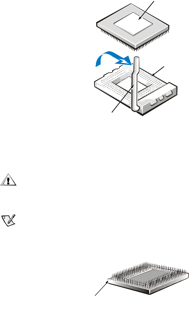
NOTE: Identifying the pin-1 corners is critical to positioning the chip correctly.
Identify the pin-1 corner of the microprocessor by turning the chip over and locat-
ing the tiny gold triangle that extends from one corner of the large central
rectangular area. The gold triangle points toward pin 1, which is also uniquely
identified by a square pad.
1"+
microprocessor
chip
microprocessor
socket
release lever
pin-1 corner
(gold triangle)