


8-14 Installation and Troubleshooting Guide
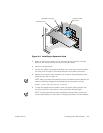
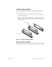
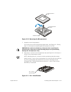
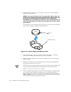
9. Install the microprocessor chip in the socket (see Figure 8-12).
#! !
! ! ,!
If the release lever on the microprocessor socket is not all the way up, move it to
that position now.
With the pin-1 corners of the chip and socket aligned, set the chip lightly in the
socket and make sure all pins are matched with the correct holes in the socket.
Because the system uses a ZIF microprocessor socket,
there is no need to use
force
(which could bend the pins if the chip is misaligned). When the chip is posi-
tioned correctly, it should drop down into the socket with minimal pressure.
#' ! %-"
%+
"
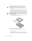
When the chip is fully seated in the socket, rotate the socket release lever back
down until it snaps into place, securing the chip.
"'%%
10. Place the new heat sink on top of the microprocessor chip (see Figure 8-12).
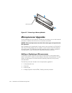
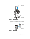
11. Replace the securing clip.
Orient the clip as shown in Figure 8-13. Hook the unfolded end of the clip over
the tab on the edge of the socket facing the bottom of the computer. Then press
down on the folded end of the clip to snap the clip over the tab on the back of the
socket.
pin-1 corners
of chip and
socket aligned