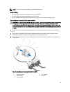
NOTE: Use alpha wire part number 3080 or equivalent (65/30 stranding)
Required Wires
• One UL 10 AWG, 2 m maximum (stranded) black wire [–(48–60) V DC]
• One UL 10 AWG, 2 m maximum (stranded) red wire (V DC return)
• One UL 10 AWG, 2 m maximum green/yellow, green with a yellow stripe, stranded wire (safety ground)
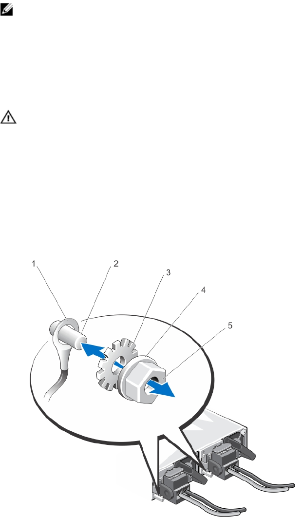
Assembling And Connecting The Safety Ground Wire
WARNING: For equipment using –(48–60) V DC power supplies, a qualified electrician must perform all connections
to DC power and to safety grounds. Do not attempt connecting to DC power or installing grounds yourself. All
electrical wiring must comply with applicable local or national codes and practices. Damage due to servicing that
is not authorized by Dell is not covered by your warranty. Read and follow all safety instructions that came with the
product.
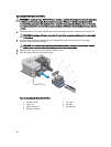
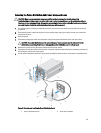
1. Strip the insulation from the end of the green/yellow wire, exposing approximately 4.5 mm (0.175 inch) of copper
wire.
2. Using a hand-crimping tool (Tyco Electronics, 58433-3 or equivalent), crimp the ring-tongue terminal (Jeeson
Terminals Inc., R5-4SA or equivalent) to the green/yellow wire (safety ground wire).
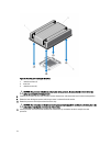
3. Connect the safety ground wire to the grounding post on the back of the system using a #6-32 nut equipped with a
locking washer.
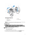
Figure 41. Assembling and Connecting the Safety Ground Wire
1.
safety ground wire
2. grounding post
3. locking washer
4. spring washer
5. #6-32 nut
79


