


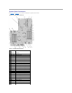
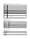

System Board Connectors
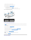
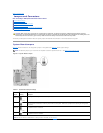
See Figure6-2 and Table6-2 for the location and description of system board connectors.
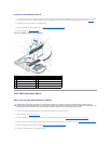
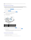
Figure 6-2. System Board Connectors
Table 6-2.SystemBoardConnectors
Connector
Description
1
RISER2
expansion-card riser 2 connector
2
MEZ_CONN
LOM daughter card
3
RISER1
Left riser board connector
4
RAC_CONN2
Remote Access Control (RAC) card 2
5
RAC_CONN1
Remote Access Control (RAC) card 1
6
BATTERY
System battery
7
TOE_KEY
TCP/IP Offload Engine Key
8
SATA_A
SATA A connector
9
B1
First memory module slot (processor 2)
10
B2
Second memory module slot (processor 2)
11
B3
Third memory module slot (processor 2)
12
B4
Fourth memory module slot (processor 2)
13
B5
Fifth memory module slot (processor 2)
14
B6
Sixth memory module slot (processor 2)
15
B7
Seventh memory module slot (processor 2)
16
B8
Eighth memory module slot (processor 2)
17
FAN4
System cooling fan
18
CPU2
Microprocessor 2
19
FAN3
System cooling fan
20
CPU1
Microprocessor 1
21
FAN2
System cooling fan
22
FAN1
System cooling fan
23
BACKPLANE
Backplane power connector
24
SIDEPLANE
Sideplane connector