9
Installation (continued)
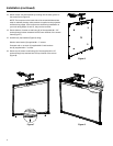
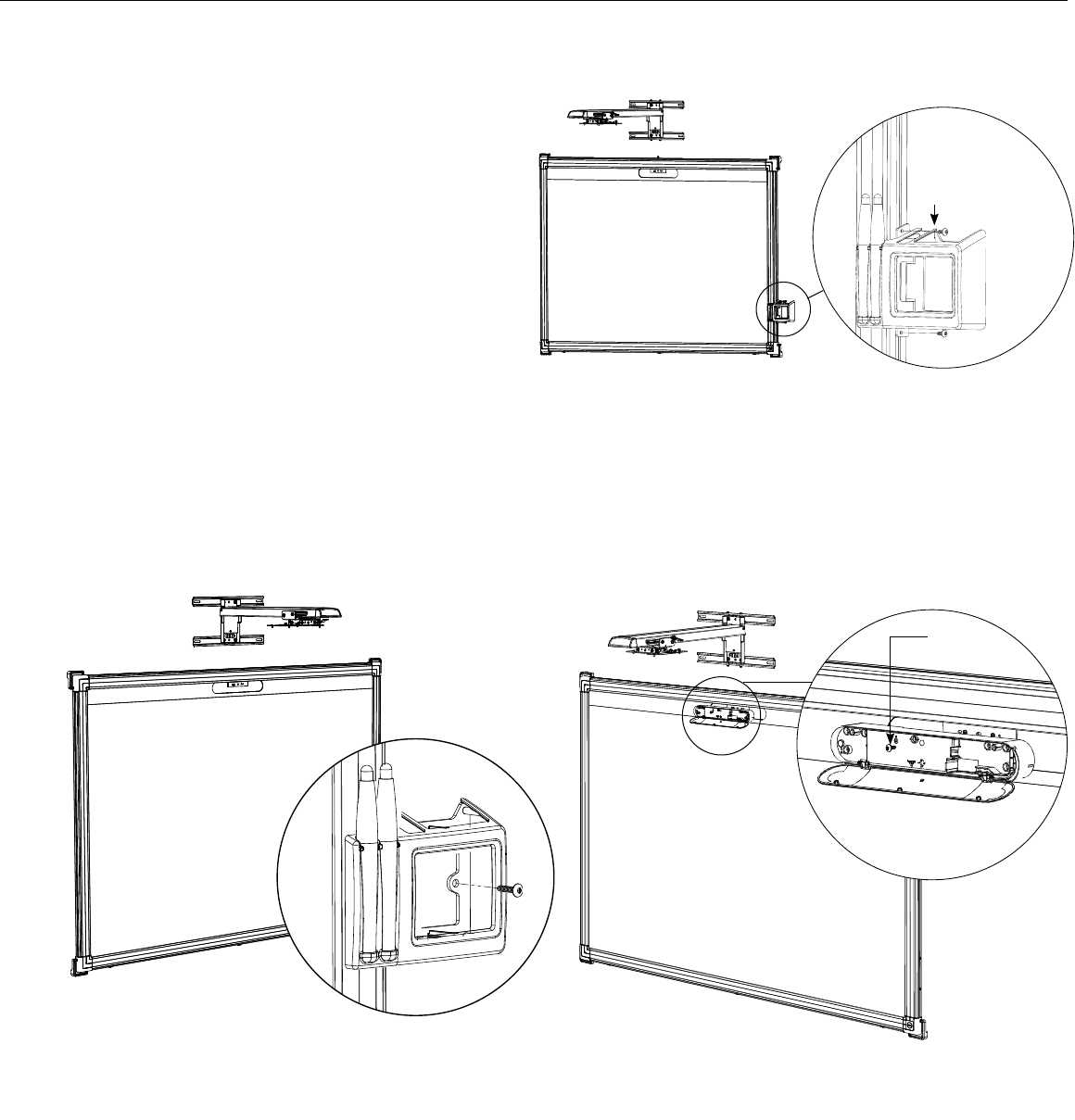
Figure 9
Figure 11Figure 10
Attach marker
tray to frame with
(2) screws into the
side channel.
Safety
Screw
17. Secure marker tray to right side of screen frame
at desired height by using (2) of the supplied
#8 x 1/2” screws into the side channel of the
screen frame (Figure 9).
18. Secure marker tray (Figure 10) to wall using:
Wood or steel studs: (1) supplied #8 x 1” screw.
Concrete wall or no studs: (1) supplied #8-10 wall
anchor and (1) #8 x 1” screw.
19. Secure IR sensor bar (packaged with the S520
Projector) to screen by sliding it onto the metal
bracket. Insert safety screw through IR sensor
bar into bracket (Figure 11).
DETAIL F
SCALE 1 : 2
F
DETAIL F
SCALE 1 : 2
F


