PD-01 PROFIBUS-DP Module
DELTA ELECTRONICS, INC. ALL RIGHTS RESERVED
31
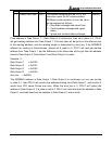
00 – Normal
01 – CRC check failure
02 – VFD series Drive returns error code
03 – Communication is time out and disconnected
Byte 9 indicates the error code when byte 8 is 02 (VFD series Drive returns error code). Refer
to the Section 6.3 for the meanings of invalid code.
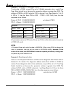
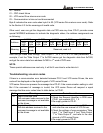
Other word, user can get the diagnostic data via PZD area any time. PD-01 provides some
special MODBUS addresses to indicate the diagnostic status, the address assignments are
as following:
0x7500 0x7501 0x7502 0x7503 0x7504
Address
High
byte
Low
byte
High
byte
Low
byte
High
byte
Low
byte
High
byte
Low
byte
High
byte
Low
byte
Meaning
SP
comm
status
Error
code
Reserved, read to 0
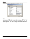
User can get these data through “Data Output 1”, or 2, or 3, or 4 in user parameters. For
example, if set the “Data Output 1” to 0x7500 means get the diagnostic data from 0x7500,
and get the return data from address 0x7500 in 1
st
word of PZD area.
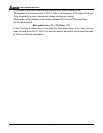
NOTE:
These special addresses are read-only, it will fail if user tries to write data to it.
Troubleshooting via error codes
If there is a communication error detected between PD-01 and VFD series Drives, the error
code will be displayed on the digital keypad of VFD series Drives.
VFD series Drives can process the message from PD-01 if the communication setting is valid.
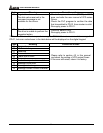
But if the command of message is invalid, the VFD series Drives will respond a report
message that has error codes listed in table below, to PD-01.
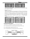
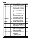
Code Meaning Corrective actives
01 Illegal command code
The command code received in the
command message is not available
for the drives.
1. Check the Request Identifier in PKW area.
PD-01 just supports ID 0, 1, 2.
2. Re-supply power to PD-01.
02 Illegal data address
The data address received in the
command message is not available
for the drives.
1. Check the Parameter number in PKW area,
and refer the user manual of VFD Drives.
2. Check the settings of user parameters “Data
Input 1” to “Data Input 4” and “Data Output
1” to “Data Output 4”, and refer to the user
manual of VFD series Drives.
3. Re-supply power to PD-01.


