


DeviceNet Slave Communication Module DVPDT02-H2
DVP-PLC Application Manual
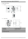
5
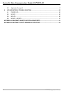
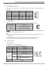
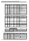
2.3 DeviceNet Connection Port
The connector is used on the connection to DeviceNet network. Wire by using the connector enclosed with
DVPDT02-H2.
PIN Signal Color Contect
1 V- Black 0 VDC
2 CAN_L Blue Signal-
3 SHIELD - Shielded
4 CAN_H White Signal+
5 V+ Red 24 VDC
1
2
3
4
5
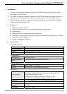
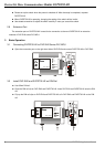
2.4 Address Switch
The switch is used on setting up the node address of DVPDT02-H2 on DeviceNet network.
Switch setting Content
0 ~ 63 Valid DeviceNet node address
64~ 99 Invalid DeviceNet node address
X
10
X
10
Example: If you need to set the node address of DVPDT02-H2 to 26, simply switch the corresponding switch
of x10
1
to 2 and the corresponding switch of x10
0
to 6.
Note:
z Please set up the node address when the power is switched off. After the setup is completed, re-power
DVPDT02-H2.
z When DVPDT02-H2 is operating, changing the set value of the node address will be invalid.
z Use slotted screwdriver to rotate the switch carefully in case you scratch the switch.
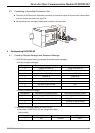
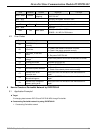
2.5 Function Switch
The switches are for:
z Setting up I/O data holding function (IN0).
z Setting up baud rates of DeviceNet network (DR0 ~ DR1).
DR1 DR0 Baud rate
OFF OFF 125 kbps
OFF ON 250 kbps
ON OFF 500 kbps
ON ON Incorrect setting
OFF
When the DeviceNet connection is
interrupted, the content in the buffer area
will not be held.
IN0
ON
When the DeviceNet connection is
interrupted, the content in the buffer area
will be held.
IN1 Reserved
DR 1
DR 0
IN 0
IN 1
Note: