


English-11
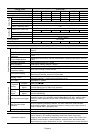
Parameter Explanation Settings
Factory
Setting
Customer
Pr.38
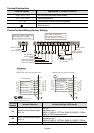
Multi-function Input
Terminal (M0,M1)
00: M0: FWD/STOP, M1: REV/STOP
01: M0: RUN/STOP, M1: REV/FWD
02: M0, M1, M2: 3-wire operation control
mode
00
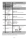
Pr.39
Pr.40
Pr.41
Pr.42
Multi-function Input
Terminal (M2)
Multi-function Input
Terminal (M3)
Multi-function Input
Terminal (M4)
Multi-function Input
Terminal (M5)
00: No Function
01: Output OFF (N.O.) (enabled when
running)
02: Output OFF (N.C.) (enabled when
running)
03: External Fault (normally open) N.O.
04: External Fault (normally close) N.C
05: RESET
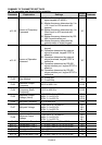
06: Multi-Step Speed Command 1
07: Multi-Step Speed Command 2
08: Multi-Step Speed Command 3
09: Jog Operation
10: Accel/Decel Speed Inhibit
11: First or Second Accel/Decel Time
12: Base-block (B.B.) (N.O)
13: Base-block (B.B.) (N.C)
14: Increase Master Frequency
15: Decrease Master Frequency
16: Run PLC Program
17: Pause PLC
18: Counter Trigger Signal
19: Counter Reset
20: No function
21: RESET command (N.C)
22: Control source: External Terminal
23: Control source: Keypad
24: Control source: Communication
25: Parameter Lock (Write disable, Read
is always 0)
26: PID Disable (N.O.)
27: PID Disable (N.C.)
28: Second Source for Frequency
Command
29: Forward (contact is open) / Reverse
(contact is close)
30: One-Shot PLC Run
31: Index input signal
32: Counter Incremented by Drive Output
Frequency
05
06
07
08
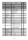
aPr.43 Analog Output Signal
00: Analog Frequency Meter (0 to
Maximum Output Frequency)
01: Analog Current Meter (0 to 250% of
the rated AC drive current)
02: Feedback signal (0 - 100%)
03: Output power (0 - 100%)
00
aPr.44 Analog Output Gain 00 to 200 % 100